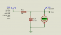
The idea is that the low pass filter will NOT allow any of the input frequencies to pass. I chose 5 Hz as it will average over 10 cycles of the lowest expected input frequency (50 Hz). I would choose a resistor value of about 10K. The microcontroller will be seeing an analogue voltage which is the average value of the PWM waveform.
The idea is that the low pass filter will NOT allow any of the input frequencies to pass. I chose 5 Hz as it will average over 10 cycles of the lowest expected input frequency (50 Hz). I would choose a resistor value of about 10K. The microcontroller will be seeing an analogue voltage which is the average value of the PWM waveform.
Everything is possible .
But you will have to initialize the ADC module and the PWM every time you want to switch from 1 to another, this will take more RAM.
Take a look at this source code with the CCS PIC C compiler from ccsinfo.com
Code:
// DC motor control using PIC16F877A CCS C code

#include <16F877A.h>
#fuses HS,NOWDT,NOPROTECT,NOLVP
#device ADC = 10
#use delay(clock = 8000000)
#use fast_io(B)
#use fast_io(C)

unsigned int16 i ;
void main(){
  port_b_pullups(TRUE);                  // Enable PORTB pull-ups
  output_b(0);                           // PORTB initial state
  set_tris_b(7);                         // Configure RB0, RB1 & RB2 as inputs
  output_c(0);                           // PORTC initial state
  set_tris_c(0);                         // Configure PORTC pins as outputs
  setup_adc(ADC_CLOCK_DIV_32);           // Set ADC conversion time to 32Tosc
  setup_adc_ports(AN0);                  // Configure AN0 as analog
  set_adc_channel(0);                    // Select channel AN0
  setup_timer_2(T2_DIV_BY_16, 250, 1);   // Set PWM frequency to 500Hz
  delay_ms(100);                         // Wait 100ms
  while(TRUE){
    i = read_adc();                      // Read from AN0 and store in i
    if(input(PIN_B3) == 1)               // If direction 1 is selected
      set_pwm1_duty(i);                  // Set pwm1 duty cycle
    if(input(PIN_B4) == 1)               // If direction 2 is selected
      set_pwm2_duty(i);                  // Set pwm2 duty cycle
    delay_ms(10);                        // Wait 10ms
    if(input(PIN_B0) == 0){              // If RB0 button pressed
      if(input(PIN_B3) == 0){            // If direction 1 not already selected
        output_b(0);                     // Both LEDs OFF
        setup_ccp1(CCP_OFF);             // CCP1 OFF
        setup_ccp2(CCP_OFF);             // CCP2 OFF
        output_c(0);                     // PORTC pins low
        delay_ms(100);                   // Wait 100ms
        setup_ccp1(CCP_PWM);             // Configure CCP1 as a PWM
        output_high(PIN_B3);             // RB3 LED ON
        }}
    if(input(PIN_B1) == 0){              // If RB1 button pressed
      if(input(PIN_B4) == 0){            // If direction 2 not already selected
        output_b(0);                     // Both LEDs OFF
        setup_ccp1(CCP_OFF);             // CCP1 OFF
        setup_ccp2(CCP_OFF);             // CCP2 OFF
        output_c(0);                     // PORTC pins low
        delay_ms(100);                   // Wait 100ms
        setup_ccp2(CCP_PWM);             // Configure CCP2 as a PWM
        output_high(PIN_B4);             // RB4 LED ON
        }}
    if(input(PIN_B2) == 0){              // If RB2 button pressed
      setup_ccp1(CCP_OFF);               // CCP1 OFF
      setup_ccp2(CCP_OFF);               // CCP2 OFF
      output_c(0);                       // PORTC pins low
      output_b(0);}                      // Both LEDs OFF
   }
}
Input PWM duty can vary from 0 to 100% and input PWM frequency can vary from 50Hz to 1KHz. This range of signal needs to be converted to DC voltage in the range of 0-5V for adc input and the after reading the adc voltage it has to be converted to pwm duty value and assigned to output pwm duty.
 Facebook
 Google
 GitHub
 Linkedin
 .
.