PWM Potentiometer

Thread Starter

samh93

Joined Oct 4, 2011
36
Hey everyone. I've just built my first pwm circuit and it works brilliantly. I can control the speed of a cooling fan and dim LED lights. The only problem is when I move the potentiometer it stops working. As long as I keep it still when rotating the switch everything works great but if I move it around or move the wires it just stops working immediately. Has anyone else experienced this before?

Thanks

Sam
 

Thread Starter

samh93

Joined Oct 4, 2011
36
I don't think so, everything's soldered nicely and its my second potentiometer. I'm using a Model AS-12 prototype board

Sam
 
I would still check all of the connections on and around the potentiometer. Basically check anything that moves with the potentiometer, both ends. I'm not sure what that board is, nothing popped up on tootle immediately. Does it have all soldered connections?
 

panic mode

Joined Oct 10, 2011
5,445
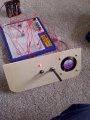
resolder all connections, make sure all wires are trimmed short and clean and no debris. make sure (i know it sounds silly) that your circuit is not resting on some metal parts like tools etc. post photo of your actual device (incl. solder side).
 

Thread Starter

samh93

Joined Oct 4, 2011
36
Okay I think I've figured it out. I re-soldered the potentiometer just to be certain but that wasn't it because it still played up. It's the prototype board (AD-12 bread board from Maplin) I opened it up and when I moved the potentiometer the wires must have lifted up slightly to disconnect the circuit, crap design if you ask me. Thanks so much for the help everyone.

Sam
 

chrisw1990

Joined Oct 22, 2011
551
ermmm right, several things..
im just having ideas here, so dont quote me on anything, but..
using these:
LED Dimmer IMAGE
And
NE555 Datasheet

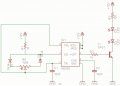
my first thought is your C1 might be too small, i think theres a frequency limit for the "modulation input" and i think your 10nF combined with the other resistances in use might be causing a too fast modulation? i know you said when you touch it, but maybe the speed of it causes instability in the modulation? have you probed it?

while im here also:
your TIP31, how much voltage have you got going through the resistor?
if the leds are red thats about 2.2V forward voltage.. so (12-0.6-2.2-2.2 = 7V across R) using v=IR.. 70mA through the diodes.. seems a lot.. and id bring that down to sub 20mA. though you will be pulsing it so you might get away with it..

personally i prefer to use an opamp for pwm (see here) much cheaper compared to the shockingly expensive 555...
 

Audioguru

Joined Dec 20, 2007
11,248
Most of my projects were one-of-a-kind. I soldered everything on stripboard where it is easy to change a part if required (but not very often). The stripboard circuits looked good enough to be sold as the finished products.

I used a prototype breadboard only one time. The circuit didn't work because there were hundreds of intermittent contacts and hundreds of wires picking up mains hum and radio transmissions from the air.
 

Thread Starter

samh93

Joined Oct 4, 2011
36
ermmm right, several things..
im just having ideas here, so dont quote me on anything, but..
using these:
LED Dimmer IMAGE
And
NE555 Datasheet

my first thought is your C1 might be too small, i think theres a frequency limit for the "modulation input" and i think your 10nF combined with the other resistances in use might be causing a too fast modulation? i know you said when you touch it, but maybe the speed of it causes instability in the modulation? have you probed it?

while im here also:
your TIP31, how much voltage have you got going through the resistor?
if the leds are red thats about 2.2V forward voltage.. so (12-0.6-2.2-2.2 = 7V across R) using v=IR.. 70mA through the diodes.. seems a lot.. and id bring that down to sub 20mA. though you will be pulsing it so you might get away with it..

personally i prefer to use an opamp for pwm (see here) much cheaper compared to the shockingly expensive 555...
Thanks for the info Chris. I'm pretty new to circuitry and the circuit diagram was one I found on the internet. I'm learning fast though so I'll be able to design my own circuit diagrams before long.

Sam
 
Top