Pulse Width Modulated Activation of Electric Motor

Thread Starter

Pawnobear

Joined Apr 25, 2017
5
Hi guys,

Need your help. I need to control an electric exhaust flap which needs a 9-16v, 100 MHz frequency and duty cycle of 10% to open and 90% to close (90 degree movement). Any ideas either a) pre-made component or b) ingredients list to make. Its the 100 MHz that is tripping me up finding a suitable fix.

Thanks, appreciate any help, guidance, thoughts.

Nick.
 

Dodgydave

Joined Jun 22, 2012
11,395
Does it not just need a DC supply between 9-16V to operate it, why must it be 100Mhz,

Is there a spec sheet for the exhaust flap?
 

Thread Starter

Pawnobear

Joined Apr 25, 2017
5
Does it not just need a DC supply between 9-16V to operate it, why must it be 100Mhz,

Is there a spec sheet for the exhaust flap?
I am upgrading the vacuum actuator valve which opens/closes the exhaust noise control valve to an electric motor version. I need to use the BMW exhaust flap actuator art no: 18308632154 (image below).


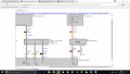
The exhaust control flap is driven via an axially arranged electric motor with integrated gearing and integrated electronics. The exhaust control flap is activated by the Digital Engine Electronics (pulse-width modulation)
Structure and inner electrical connection
The electric exhaust control flap is connected via 4-pin plug connection. The drive for the electric exhaust control flap is supplied with terminal 15N.

The exhaust control flap can be opened (10% PWM) and closed (90% PWM). The end positions are mechanical limit stops. Intermediate positions are not provided. The preferred position with a detected fault (for example failure of PWM signal) or after switching off the internal combustion engine is the opened position.

upload_2017-4-26_6-0-6.png


Item Explanation Item Explanation
1 Electric motor for electric exhaust control flap
2 Electronic component with evaluation electronics

Pin assignments

Pin Explanation
Kl. 15N Terminal 15, voltage supply
Terminal 31L Load ground
PWM Pulse-width modulated activation of electric motor for electric exhaust control flap
Nominal values
Please observe the following setpoint values for the electric exhaust control flap:
Variable Value
Voltage range 9 to 16 volts
Duty cycle 10 to 90%
Frequency 100 MHz
Temperature range -40 °C to 140 °C

https://www.newtis.info/tisv2/a/en/...lectronics/exhaust-emission-system/1VnYLMv5po
https://www.newtis.info/tisv2/a/en/...-electronics/exhaust-emission-system/Im2GgsKi

Thanks for your help guys.

Nick.
 
Last edited:

dendad

Joined Feb 20, 2016
4,636
WoW.
The info says 100Mhz. That is a radio transmitter! I wonder why they need that sort of frequency? Anyone have an idea?
 

dendad

Joined Feb 20, 2016
4,636
That's what I reckon too.
So Pawnobear, are you going to have a go at the 4093 or 555 circuit to see how it goes?
It does look like there may be some driver electronics in the device so a power transistor probably is not needed.
Try running it all on 12V and driving the PWM pin from your 555 or 4093 circuit via a 1K resistor and see what happens.
 

Thread Starter

Pawnobear

Joined Apr 25, 2017
5
That's what I reckon too.
So Pawnobear, are you going to have a go at the 4093 or 555 circuit to see how it goes?
It does look like there may be some driver electronics in the device so a power transistor probably is not needed.
Try running it all on 12V and driving the PWM pin from your 555 or 4093 circuit via a 1K resistor and see what happens.

I think I will give Crutschow's 4093 a go, glad it was not just me thinking 100 MHz was typo. Thanks for the help Dendad, really appreciated and will update with results asap.

Cheers guys

Nick.
 

crutschow

Joined Mar 14, 2008
38,481
If you want ≈5kHz as Max suggested, using the 4093 circuit, change C1 to about 5nF or the pot to 20kΩ and C1 to 24nF.
 
Last edited:

MaxHeadRoom

Joined Jul 18, 2013
30,627
The servo in RC has an internal coincidence pot, for feedback, as opposed to the ESC controller which controls the motor and can be BLDC with no F.B.
Max.
 

Thread Starter

Pawnobear

Joined Apr 25, 2017
5
If you want ≈5kHz as Max suggested, using the 4093 circuit, change C1 to about 5nF or the pot to 20kΩ and C1 to 24nF.
Thanks crutschow,

Taking that thought a wee bit further, I may as well build one at 100kHz (assuming the original spec of 100mHz is typo and 100Hz too low)? What cap and pot mix would best suit? I have no means to test other than plug into the motor and trial by fire so popped into my head about some means of readout/display/etc to advise duty cycle, is this possible or am I getting way over my head?

Cheers guys

Nick.
 

JWHassler

Joined Sep 25, 2013
308
Here's a factory(?) reference to using 200Hz for exhaust flap operation.
Armed with this supposed insight, I would say that using 100KHz would be subject to interference problems. The response-time would be pointlessly faster.
Any chance of looking at the signal with a scope?
 
Top