Pulling a mV signal out of the Noise

Thread Starter

SamR

Joined Mar 19, 2019
5,542
@OBW0549 I was wondering about the PSU which is a switching mode PSU. Yes, I completely understand the 60hZ noise. I will have to give some thought and possibly invest in a good non-switching PSU and after I complete the new desk/bench project was considering a 2nd PSU so a good non-switching regulated PSU needs to be considered. Thx!

EDIT: I was wrong! The Korad KD3005D PSU that I have IS a linear PSU. Somehow I was thinking it was a switching mode.
 
Last edited:

crutschow

Joined Mar 14, 2008
38,913
Does your oscilloscope have a variable persistence mode that can be used to average the signal?
If so, you could try externally syncing the scope to the signal source and vary the persistence to see if that helps.
 

SLK001

Joined Nov 29, 2011
1,549
No dedicated ground other than the 120V panel ground ATM. I could cobble something up a try it. Going out for lunch w/ the "boys" in a bit so will give it a shot later and see. Thx for the suggestion!
That's not the ground I'm referring to. Use CIRCUIT ground - it's as simple as a black lead from your PS to the sheet of metal.
 

Audioguru again

Joined Oct 21, 2019
6,826
If the power cord on the 'scope has only two pins then try turning it around.
I think your transistor circuit is built on a Mickey Mouse solderless breadboard with its many strips of contacts and wires all over the place acting like antennas that pickup all kinds of interference.

Do you have a shielded audio cable between the signal generator and the transistor input capacitor?

Oh, maybe the problem is caused by the same poor soldering as on the chaser circuits you built?

I simulated your transistor circuit and it works perfectly, 10mV p-p input produces an output from 6.7V to 8.9V (voltage gain of 220 times with no load).
 

Wolframore

Joined Jan 21, 2019
2,619
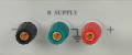
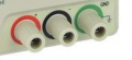
@SamR are you using chassis ground connection out of your DC supply? I've seen ground noise like this from doing that. The middle connection is chassis ground... do not use.


1571852449009.png

or in your supply the last one...
1571852561910.png

all these updates, I can get the images to line up correctly.
 

Thread Starter

SamR

Joined Mar 19, 2019
5,542
@Audioguru again Do you have a shielded audio cable between the signal generator and the transistor input capacitor?
I assume it is, it connects with BNC then has ~2-3' cable section then a fused plastic section with maybe 10" red and blk wires with a minigrabber on each.

many strips of contacts and wires all over the place acting like antennas that pickup all kinds of interference. That is the case...

Oh, maybe the problem is caused by the same poor soldering as on the chaser circuits you built? ?
Not me? It is on a breadboard for experimental use.

I simulated your transistor circuit and it works perfectly, I have not put it into LTC yet and it is from Grob's Basic Electronics so I had no doubt it would simulate. Which transistor did you use? So far I have tried the A42, BC107, and 2N2222A and only getting ~40mA from the 10mA output. Just got back from lunch w/ the guys so still need to do some work on it.

@Wolframore No, only + & - connections from linear PSU to breadboard. PSU set for 15VDC and only pulls ~5mA.

@Yaakov Interesting read. Now everything is powered from a shared 20A wall outlet which feeds into a filtered UPS. Not all of its outlets are UPS and the non-UPS filtered outputs feed 4 - 6 outlet suppressed/filtered/fused/switched power strips. It's a real snake-pit of wiring although not everything is on at one time. The PSU, Function Generator, and Scope are all on the same circuit w/ ~6' of wiring between them, so they are about as close as possible. When my new desk/bench project is finished it has its own dedicated 20A outlet plus a shared 20A outlet to feed it. Then I will have to give some thought as to power distribution.

@crutschow variable persistence mode that can be used to average the signal? It does and hadn't even considered it. Will have to look into it. I am averaging the signal 16 times already and thought of the persistence as a holdover from CRT days and of not much consequence for a digital scope. Averaging slows things down and I rarely use more than 16 to average and rarely that as 4 times seems to work when I do need to quiet a signal down which is not very often.

Thx for the input guys! Sam
 

tautech

Joined Oct 8, 2019
507
Sam, don't discount there isn't a SMPS wallwart nearby that's the cause of all this.
Sometimes ditching the probe reference (ground) lead in favor of the tiny spring lead will overcome local EMI issues.

The only nuisance using one is you have to ditch the probe hook top hat in order to fit the spring lead.
 

Thread Starter

SamR

Joined Mar 19, 2019
5,542
@tautech don't discount there isn't a SMPS wallwart nearby You may have hit the nail on the head! I had not even considered that and there are ~4+ wallwarts on this piece of the power circuit even though it is filtered on the input side of it they are on this side of the filter which only has surge suppression.
 

tautech

Joined Oct 8, 2019
507
Suggested little learning/awareness exercise:
Set probe and scope input to 10x. Clip probe reference/ground lead to probe hook....(classic RF loop probe)
Set high sensitivity on scope.
Start wandering it around your lab to examine the RFI/EMI from all sorts of sources.....even the scope itself !

Basically anything with a switcher can give you grief but some much more so than others.

I encounter this occasionally with customers thinking there's something wrong with the scope I've sold them.
 

Audioguru again

Joined Oct 21, 2019
6,826
@Audioguru again Do you have a shielded audio cable between the signal generator and the transistor input capacitor?
I assume it is, it connects with BNC then has ~2-3' cable section then a fused plastic section with maybe 10" red and blk wires with a minigrabber on each.
10"' of an antenna is not what you need, ALL the wiring must be shielded to avoid interference pickup.

It is on a breadboard for experimental use.
Get rid of the Mickey Mouse solderless breadboard and use a compact pcb or compact stripboard layout instead.

I simulated your transistor circuit and it works perfectly, I have not put it into LTC yet and it is from Grob's Basic Electronics so I had no doubt it would simulate. Which transistor did you use? So far I have tried the A42, BC107, and 2N2222A and only getting ~40mA from the 10mA output.
A 2N222A will work the same as the 2N3904 that I used in my simulation. I do not know what is a A42 is but the pins on an old BC107 must be what is shown on its datasheet. The tab on the metal can is nearest the emitter wire.
The transistor does not have a 10mA output and draws only about 7mA certainly not 40mA from the power supply.
 

Thread Starter

SamR

Joined Mar 19, 2019
5,542
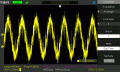
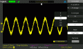
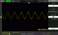
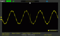
OK after a lot of tweaking and filtering on a 10mV @ 10kHz input signal this is what I can get.

1.gif2.gif3.gif4.gif5.gif6.gif7.gif

There is still an issue with the output signal that I am still working on...
 

Thread Starter

SamR

Joined Mar 19, 2019
5,542
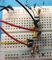
Signal input across 100nF coupling cap and scope probe on base. mA meter across base to xstr. Emitter w/ 100nF cap.
ceamp.jpg
 

Audioguru again

Joined Oct 21, 2019
6,826
Your transistor circuit shows two red antenna wires that will pickup all kinds of interference at low levels. Your generator output and 'scope input must be completely shielded wires. I do not see where the base resistors are connected to the + power supply and to 0V. What is the DC voltage at the collector of the transistor?

Why do you feed the signal into the input capacitor then 'scope the same signal at the output of the input capacitor? Then you have TWO antenna wires to pickup lots of interference.

I get it. Your mA meter is SHORTING the base to the emitter of the transistor. Then the transistor is turned off and does not amplify anything.

I guess the emitter capacitor is 100nF. Then it cuts frequencies below 33kHz and 6.67kHz will be 0.707 times the output at very high frequencies. Use 22uF 1000uF for the transistor to have a high output level of most audio frequencies. Corrected.
 
Last edited:

Thread Starter

SamR

Joined Mar 19, 2019
5,542
@Audioguru again two red antenna wires that will pickup all kinds of interference at low levels
The bottom red one is the 10mA signal input and the red above that is the mA measuring the base input.

I do not see where the base resistors are connected to the + power supply and to 0V.
The 2 resistors at the bottom. 18k to + rail and the 3.6k to the - rail. The 2 yellow jumpers across the middle do nothing and are leftovers from moving the xstr around.

What is the DC voltage at the collector of the transistor? 7.53V

Why do you feed the signal into the input capacitor then 'scope the same signal at the output of the input capacitor? Then you have TWO antenna wires to pickup lots of interference.
The Yellow and Red on the bottom left are the scope and signal input connections in front of the coupling capacitor to the base.

Your mA meter is SHORTING the base to the emitter of the transistor NO! the meter is across the middle trough connecting the base resistors to the xstr base.

emitter capacitor is 100nF. Then it cuts frequencies below 33kHz and 6.67kHz will be 0.707 times the output at very high frequencies. Use 22uF for the transistor to have a high output level of most audio frequencies.
OK I missed that. The cap values were not given and when I looked at coupling caps for 1-10kHz I came up with ~0.1 - 1uF. I'll put a 22uF in.

That pulled the Vc down to 7.31V w/ 23uA Ib and 2.41V Vb
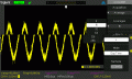
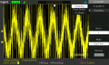
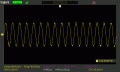
And it came back up to 7.6V and AC output swinging from 40mV up to 400+mV which could be an artifact of the averaging and unsteady output signal. Going up and down like a Yo-Yo. Seems like it may even be inverting at the bottom.
SDS00001.gif
 

Audioguru again

Joined Oct 21, 2019
6,826
Why are you measuring the transistor base current? The unshielded wires to the current meter are antennas that pickup all kinds of interference. Use a short jumper wire instead.

Your breadboard circuit is missing an important supply bypass capacitor. Use 220uF.
 

Thread Starter

SamR

Joined Mar 19, 2019
5,542
@Audioguru again Why are you measuring the transistor base current? Because I was comparing meas vs. calc values and never put the jumper back. Now that I have the output is really swinging up to ~1.5Vpp.

missing an important supply bypass capacitor. Use 220uF I put in a 22uF lyt now 220uF? OK that got it swinging from ~0.4V to up just over 2Vpp. It does not appear steady on the scope but it is putting out an amplified signal. I could put it out to a speaker to see how steady it is but that is more than I planned for on for a simple exercise... I am working on a sensitive audio detector project but don't have all the parts for it yet, now is when I could really use it. K what did I miss on the emitter cap? And many thx for all the help, I really do appreciate your time.
 

Audioguru again

Joined Oct 21, 2019
6,826
The simple transistor is a preamp, not a power amp so it cannot drive a speaker. A speaker is 4 ohms or 8 ohms but this preamp can drive the input resistance of 10 thousand ohms of a power amplifier.

For the value of the emitter capacitor you missed calculating the RC low frequency cutoff calculation.
I also missed the calculation for the cutoff frequency of the emitter capacitor. It should be 1000uF.
At 30Hz the reactance of the emitter capacitor must be the same as or less than the internal virtual emitter resistance of the transistor, for an output level that is at -3dB which is 0.707 times.
 
Top