PT2399 audio processing chip for electric guitar pedal

Thread Starter

Willen

Joined Nov 13, 2015
333
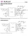
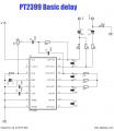
Hi all, I am trying to make a reverb pedal for someone to get reverb/delay/echo effect for an electric guitar (Chinese copy of Fender guitar). But I don't know about input and output impedances. So can I add the the circuit (device) between Guitar and Amp? I hope output and guitar and input of Amp have nice match to the PT2399 circuit. Some circuits has extra OpAmp too. But for the guitar pedal, if I don't need, I won't go through the OpAmp.
 

Attachments

bertus

Joined Apr 5, 2008
22,270
Hello,

Perhaps you can get some ideas from the attached PDF.
And here is a page with a lot of info:
https://diyaudiocircuits.com/pt2399-digital-delay-analog-echo/
Some more:
There seems to be a throughhole version of the PT2399 available.
On this site it is used in a board they show:
https://www.synthrotek.com/kit-asse...-kits/pt2399-dev-delay-assembly-instructions/
On ESP also aproject is given:
https://sound-au.com/project26a.htm
Peter Vis also has some pages:
https://www.petervis.com/guitar-circuits/pt2399/overall-configuration.html

Bertus
 

Attachments

Ian0

Joined Aug 7, 2020
9,667
There's something a bit weird about your circuit - the output seems to be connected to the VCO.
Here's the real datasheet.
http://www.princeton.com.tw/Portals/0/Product/PT2399-s.pdf
The input circuit is a MFB filter (anti-aliasing filter), which is also a mixer which mixes the input signal with the delayed signal.
As it's an MFB filter the input is a virtual earth, so the input impedance is 15k (on their application circuits)
You need about 500mV rms input signal.
With about 30mV from a guitar pickup you need some amplification, and you need a much higher input impedance; though if you want to keep extra components to a minimum, you could reduce the value of the input resistor (thus increasing the gain) and just buffer the guitar signal with a JFET.
Princeton claims a S/N ratio of 90dB, but I think they may be pushing their luck with that one! Even so, I don't remember it being noisy.
The output comes from an op-amp, so the output impedance would be quite small, but the signal level would be rather to high to drive the input of a guitar amp, so you would need some attenuation.
 

Ian0

Joined Aug 7, 2020
9,667
I use a J113 as a source-follower. For a guitar pedal with a single-ended 9V supply, it conveniently level-shifts to somewhere near half-supply.
 

Thread Starter

Willen

Joined Nov 13, 2015
333
I use a J113 as a source-follower. For a guitar pedal with a single-ended 9V supply, it conveniently level-shifts to somewhere near half-supply.
That's needed for guitar signal buffer? Do you have exact schematic?
 

Ian0

Joined Aug 7, 2020
9,667
Screenshot at 2021-04-14 07-54-37.pngR5 and L1 are the pickup resistance and inductance
C2 is the cable capacitance
The op-amp is part of the PT2399 so the rest of the biassing is not shown.
I find a load resistance of 220k works better than the usual 1M because it tends to damp the pickup-inductance/cable-capacitance resonance which intrudes at a few kHz, and depends on the cable.
I'm not sure this will have a big enough signal for the PT2399, but I think it's worth a try. Otherwise, you could perhaps use the JFET as a simple amplifier to give it a bit of gain, but I've not tried that.
Originally, I used a TL074 with one section as the input buffer. Then I found I needed four op-amps for the rest of the circuit, and didn't want to buy a TL071 just for the input, hence the JFET circuit.
 

Thread Starter

Willen

Joined Nov 13, 2015
333
View attachment 235311R5 and L1 are the pickup resistance and inductance
C2 is the cable capacitance
The op-amp is part of the PT2399 so the rest of the biassing is not shown.
I find a load resistance of 220k works better than the usual 1M because it tends to damp the pickup-inductance/cable-capacitance resonance which intrudes at a few kHz, and depends on the cable.
I'm not sure this will have a big enough signal for the PT2399, but I think it's worth a try. Otherwise, you could perhaps use the JFET as a simple amplifier to give it a bit of gain, but I've not tried that.
Originally, I used a TL074 with one section as the input buffer. Then I found I needed four op-amps for the rest of the circuit, and didn't want to buy a TL071 just for the input, hence the JFET circuit.
Feeling wow! I will omit before R2 and after R3 and wilk use the JFET circuit to feed the PT2399 circuit posted in first post. But being in a remote place, I cannot get desired parts when I need them. Years ago, someone from west part of the world had gave me 11 pieces of J201 JFETs. Thinking that the JFETs are really amazing thing, I have kept all of them safe till now. I checked the datasheet and your JFET has 2mA Idss at 15V and mine has 1mA Idss at 20V. Can I replace the J201 there?
 

Ian0

Joined Aug 7, 2020
9,667
There's a very good chance it will work.
The circuit in the first post is wrong - use the one from the Princeston datasheet.
 

bertus

Joined Apr 5, 2008
22,270
Hello,

With an echo, the origenal singal is mixed with the delayed, as output.
With delay, only the delayed signal is on the output.

Bertus
 

Ian0

Joined Aug 7, 2020
9,667
And with reverb, it is a mix of original and several different delays. The PT2399 achieves this by sending a proportion of the output signal back through the delay again.
 

Thread Starter

Willen

Joined Nov 13, 2015
333
Ok then the echo (1st circuit in the #11 post) sounds better for the reverb effect pedal. The 2nd has a term "sorround" which also looks like a reverb? Anyway, the chip needs 5V and the JFET booster needs 9V. I am planning to use 9V SMPS adapter to feed JFET booster and regulated 5V for the processing chip (or regulated 5V works for JFET too?) . But in critical circuit, SMPS creates huge noise. Do I need to worry about it?
 

Ian0

Joined Aug 7, 2020
9,667
Definitely a job for a linear regulator. The PT2399 needs quite a bit of current (30mA), so a PP3 will barely get you through one gig.
 
Top