PSpice Bandpass Filter

Thread Starter

spiralup

Joined Dec 1, 2014
2
I am trying to design an active band-pass filter with center frequency of 6.8MHz, bandwidth of 17kHz, and a gain of 14.
I used these values (14= (Rf/R1) +1)to select the resistors for the gain. I chose Rf to be 1300 and R1 to be 100.
Since BW = R/L, I chose R to be 170 and L to be 0.01. C was found to be 2.16E-12 (this is a bit suspicious to me, but it is what I have repeatedly calculated from center frequency = (R/2L) + (sqrt(R^2C^2+4LC)/2LC)).


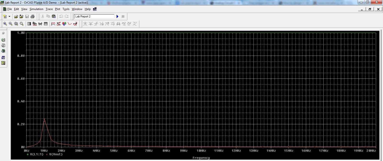
I used a VAC source. The AC analysis from 10k to 20M yielded this linear plot:


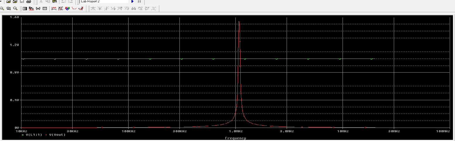
and this decade plot:


For the linear plot, shouldn't taking 20*log[Vout/Vsource] yield the bode plot?

Both are giving an odd spike in the Vout around 1 MHz. It needs to be 6.8 MHz though. Changing the value of C did move the spike closer to 6.8MHz, but 2.16E-12 was my calculated value. I am not sure what to try next.
 

crutschow

Joined Mar 14, 2008
34,432
That is not an active bandpass filter, it is a passive LC filter followed by an op amp with a gain of 131. For that you would need a voltage-feedback op amp with a gain-bandwidth-product of 891MHz. Since such high frequency voltage op amps are rare (if they exist at all) you will likely need a current-feedback type op amp to get that gain at 6.8MHz.
 

Thread Starter

spiralup

Joined Dec 1, 2014
2
What kind of opamp are you using? It's a pretty rare opamp that is going to have a 90 MHz GBWP.
Thank you for the response!
I was just using the (ideal?) op-amp in the PSpice Schematics library (the one that is not the UA741). Could it be that I was given these values in this assignment even though this simulator --and others--cannot compute this? The instructions seemed pretty clear that I was supposed add an passive RLC series filter to a non-inverting op-amp to from a bandpass filter that has gain. I guess I will throw the instructions out and just try to get any circuit that can handle these values, heh.

That is not an active bandpass filter, it is a passive LC filter followed by an op amp with a gain of 131. For that you would need a voltage-feedback op amp with a gain-bandwidth-product of 891MHz. Since such high frequency voltage op amps are rare (if they exist at all) you will likely need a current-feedback type op amp to get that gain at 6.8MHz.
Thank you for the response!
I believe the gain is 14. Gain = (1300/100) +1
I will look into this and reply back.
 

WBahn

Joined Mar 31, 2012
30,058
That is not an active bandpass filter, it is a passive LC filter followed by an op amp with a gain of 131. For that you would need a voltage-feedback op amp with a gain-bandwidth-product of 891MHz. Since such high frequency voltage op amps are rare (if they exist at all) you will likely need a current-feedback type op amp to get that gain at 6.8MHz.
How are you getting a gain of 131? I get a gain of 14. I think you looked at the resistor values a bit too quickly (happens).
 

WBahn

Joined Mar 31, 2012
30,058
Since it is not an active filter you have some options. First, plot the frequency response at the non-inverting input of the opamp (I would even remove the opamp entirely for this part). See if that is what you are looking for (other than the gain). Then apply an ideal sinusoidal source directly to the non-inverting input of the opamp and see what the frequency response is of whatever opamp model is being used.
 
Top