PSPICE amplifier circuit problem

Thread Starter

Rated007

Joined Dec 21, 2014
4
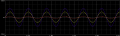
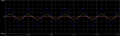
As shown in the attached files, I created an amplifer circuit using an inverting amplifier as the pre amp and a class AB circuit for the power amp. I used a voltage divider to supply 4.5V. My pre amp works fine. But the amplitude of the output of the power amp is very much lower than i want it to be. I can fix this upto a certain extent using low resistor values for the voltage divider but then those resistors get immensely heated up and also, the phase shift alters. So can someone please provide me a solution as to how i can modify my circuit to get a well amplified and less noise distorted output. The IC used is LM324 and the resistance of the output speaker is 8 ohms. The pspice schematic and simulation are attached below. Thank you very much
 

Attachments

Thread Starter

Rated007

Joined Dec 21, 2014
4
Hi eric,
What's the best alternate solution? Is it possible to change the resistor values to resolve this issue? Thank you.
7.
 

Alec_t

Joined Sep 17, 2013
14,280
Welcome to the forum!
R8 and R9 are not needed.
Check the datasheets for the 2N3904 and 2N3906! They have a maximum collector current rating of 200mA and are unsuited to driving an 8 Ohm load, as is a 9V PP3 battery.
 

bertus

Joined Apr 5, 2008
22,270
Hello,

You will have to remove R8 and R9 (both 330 Ohms at the output of the virtual ground circuit).

If you want to have a more stable virtual powersupply, have a look on this project:
CMV2A virtual ground circuit

As said a 9 Volt PP3 battery wont last long.

Bertus
 

Thread Starter

Rated007

Joined Dec 21, 2014
4
Hi bertus,
thank you for the info but its compulsory for us to use the configuration of my schematic. So if its possible could you please let me know how i can improve my circuit without making heavy alterations to it.
Thank you
7.
 

bertus

Joined Apr 5, 2008
22,270
Hello,

Did you have a look at the schematic I pointed you?
The input resistors there are 10 K in stead of the 100 K you are using.
Also there are capacitors accross the resistors, any value between 10 and 100 nF will do.

Bertus
 

ericgibbs

Joined Jan 29, 2010
18,766
What's the best alternate solution? Is it possible to change the resistor values to resolve this issue? Thank you.
hi 7,
By using AC coupling throughout the amplifier and to the 8R speaker, via say a 1000uF, you could eliminate the need for a virtual ground source.
Use BD135 and BD136 transistors to make a medium power audio amp

The 9V, PP9 battery will have a short life!

E
 

Alec_t

Joined Sep 17, 2013
14,280
You could also use BD135/136 or similar transistors as a push-pull output stage to boost the current available from your virtual ground circuit.
 
Top