 Facebook
 Google
 GitHub
 Linkedin
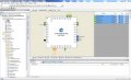
PSOC Logic Trainer
- Thread starter danadak
- Start date

| Thread starter | Similar threads | Forum | Replies | Date |
|---|---|---|---|---|
| S | Understanding the Linker Script in PSoC Creator Cypress Dock Project | Software & IDEs | 4 | |
|
|
PsOC 4 BLE (pins problems) | Wireless & RF Design | 0 | |
| S | Simulate PSoC in Proteus | PCB Layout , EDA & Simulations | 3 | |
|
|
PSoC KitProg Question | Microcontrollers | 2 | |
|
|
A couple of newbie questions about PSoC | Microcontrollers | 13 |


