Projector Trigger Circuit

Thread Starter

boon147

Joined Sep 1, 2018
9
Afternoon all,

Hope you are well.

I am trying to work out how to create a trigger circuit for my projector screen. To give you a bit of background, I already created one successfully at my old house, however I am hoping to improve on it.

My projector has a 12v Trigger output (but screen does not have an input), which used to be connected to a relay, and then the Live Up / Live Down of the screen were connected to NO / NC as required.

Occasionally after the screen rolled up, the motor would start to whistle (after a period of time) and would disappear if I rolled it down and back up quickly (almost as if I was 're-seating' the motor). The reason this doesn't happen with the included control box, is because the internal relay within the control box automatically switches off the Up or Down power after approximately 5 minutes, where as my basic 12v relay didn't, and supplied a constant source of power to either one of the Up or Down lines.

What I am now hoping to achieve, is a MK2 version where I could use a timed relay that will cut the power after approximately 5 minutes. Unfortunately, I don't think this will work as my understanding is that a timed relay will switch back to NC when the timer runs out, defeating the object as it would cause the screen to roll back up when it is still in use.

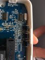
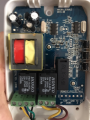
The other solution I considered is to use the internal circuitry of the control box, as it already does what I want, so therefore it exists,..somewhere. This is where my knowledge ends, and I'm turning to you experts to advise me accordingly. I have attached some photos of the control box, and also noted that there is a un-used connection on the bottom left, that allows some form of wired remote to be connected to it. I had a hunt, but unfortunately was unable to find any documentation on the unit, and what I need.

Look forward to your response.

Kind Regards,

Paul
 

Attachments

MisterBill2

Joined Jan 23, 2018
27,514
What I see is that there are already remote control connections to the controller module, and I recommend using them. And the connection points are clearly marked. No reason to do it any other way.
 
Last edited:

Thread Starter

boon147

Joined Sep 1, 2018
9
What I see is that there are already remote control connections to the controller module, and I recommend using them. And the connection points are clearly marked. No reason to do it any other way.
Thanks for the swift reply. The reason I previously used the12v trigger was because my projector already had it, however totally agree the better solution would be to use the remote control pin outs and I’m wanting to make this a better solution, so need to turn to you guys for assistance.

Unfortunately this is where my knowledge ends and the documentation I found is limited. The connector is titled REMOTE/RS232/485. It looks like it can use a number of protocols, and from my understanding; out of the 6 pins, 1 - 4 will be used for some form of wired remote, and pins 4-6 will be for RS232/485 protocol.

I’ve not really dabbled much into RS controlling as I don’t have the gear to do it, and understand for this tiny requirement, I’ll need another piece of hardware, which brings me back to using pins 1 - 4 as I believe I could manipulate the trigger to send UP and DOWN commands (don’t need stop, I’ll use that on the RF remote for manual maintenance).

Providing that the remote connection header just takes a voltage pulse (which it normally would with a wired remote and these screens) then I can use the 3 pins in the 3.5mm cable already hidden in place, to provide GND, UP and DOWN.

What would be my next step, how would I check what voltage Pin 1 - 4 accept? I don’t want to blow / fry any of the components in the control box so don’t want to to start just poking around in there. I suppose I could look to slowly increas the voltage in each attempt before it triggers.

Many thanks for your help

Regards,

Paul
 

bertus

Joined Apr 5, 2008
22,923
Hello,

What I see is that quite some components positions are not populated.
Most of them are in the remote control area.
It looks like the remote control part is not available.

What are the functions of the switches K101, K102 and K103?

Bertus
 

Thread Starter

boon147

Joined Sep 1, 2018
9
Hello,

What I see is that quite some components positions are not populated.
Most of them are in the remote control area.
It looks like the remote control part is not available.

What are the functions of the switches K101, K102 and K103?

Bertus
Yes I thought that too, as there seems to be (at the very least) some form a chip missing.

K101 - 103 are set of switches for UP, DOWN, and STOP in case the RF remote isn’t available. Thinking with my limited hat on, could this mean that the missing components could be purely for the RS323/485? If the buttons exist, could the core circuit exist for the wired remote?

I suppose I could measure the voltage over UP and GND when I press the button, to see if it’s connected? Failing that, maybe I could utilise the solder points of the K switches?

If all goes well, the only potential stumbling block I see is that the 12v trigger from the PJ would supply constant power for the duration while it’s switched on, which would be the equivalent of the K button being constantly pressed. I’m wondering if this would affect the way the internal relay behaves, when it cuts power to the motor after a certain amount of time (I think it’s 5 minutes).

Many thanks,

Paul
 

bertus

Joined Apr 5, 2008
22,923
Hello,

Are thosse buttons currently used to control the screen?
If so, you could use some mosfet opto's accross the switches for external control.

Bertus
 

MisterBill2

Joined Jan 23, 2018
27,514
What I see in the one photo that shows the connections is both positions for the serial control connections AND connections for the direct remote control points. THAT is what I was referencing. It should be simple to attach some connections to those points and try to see if they work. Three would be required, Up, Dow, and Gnd. It may also be informative to see if those have a direct connection to the push button switch terminals. Worst case would be if you had to connect your control relay contacts directly across the button terminals, because you would need to use 4 wires and have the connections isolated from everything else.
 

Thread Starter

boon147

Joined Sep 1, 2018
9
Hello,

Are thosse buttons currently used to control the screen?
If so, you could use some mosfet opto's accross the switches for external control.

Bertus
Yes, they are used sometimes when the RF has been misplaced by my 3 year old. I have just had a prod around with my multimeter and detailed my findings in the below reply.

What I see in the one photo that shows the connections is both positions for the serial control connections AND connections for the direct remote control points. THAT is what I was referencing. It should be simple to attach some connections to those points and try to see if they work. Three would be required, Up, Dow, and Gnd. It may also be informative to see if those have a direct connection to the push button switch terminals. Worst case would be if you had to connect your control relay contacts directly across the button terminals, because you would need to use 4 wires and have the connections isolated from everything else.
OK, so I'm hoping that I'm a little further on to designing the correct circuit / relay setup. So the RS232/485 Tx & Rx points are dead, and show no reading at all. However, pins 1 - 4 show a constant 5v, which then drops to 0v when the switch is pressed. This drop is for as long as the button is pressed. For example, if I measure DOWN & GND, and press and hold the down button, the voltage will drop to 0 until I release the button. As you quite rightly pointed out, I will only need to use 3 points, so the integration into my 12v circuit could still be a suitable one, as I could use to timed relay to momentarily control NC & NO which would be reference to UP and DOWN.

I am not young by any means, but I am still studying my electronics and am very much in my infancy in that respect. So please correct me if I am wrong at any point, but I would need a relay / device that will effectively bring the voltage to 0v on these points?

Is that any clearer for you all?

I am not sure what the TS is trying to do. However, here are some links to pdf that might be helpful:

http://www.cinemasource.com/articles/screen_wire.pdf

http://ytk.com.hk/userfiles/RF-A232 Remote Control Manual.pdf
Many thanks for the links, I'll look at them now after posting this reply.

Many thanks already for all your help everyone, I do really appreciate it.

Regards,

Paul
 

MisterBill2

Joined Jan 23, 2018
27,514
OK, the good news seems to be that the connection points are active and only the comm points would need more parts. So now it becomes a situation of adding connections to some isolated relay contacts. That should be a lot simpler than designing a whole motor control system, and also a lot less costly.
This is a result of providing adequate information to the folks attempting to provide useful answers!
 

Thread Starter

boon147

Joined Sep 1, 2018
9
Afternoon all,

Sorry for the delayed reply, I have been working away all week and have not long been back.

Have been researching all week while I've been away, and can now confirm (after testing) that the connection points are an exact mirror of the switch circuit. I can bridge DOWN and GND and the screen will drop, however just as the button, will only drop once the wire / bridge is removed.

I initially thought about some form of pulse to activate the circuit, which would work. However, this would be no improvement over my initial setup at the old house, because this would mean that that internal timed relay would reset each time the pulse drops meaning that the relay would never switch of the power to the motor, and I would then get the whistle back.

So, my final dilemma is now how to get an ON / OFF 12v circuit trigger, to bridge 3 points on the control panel motherboard. This is where I need more help from you guys as I think I know what I need, but may need a gentle nudge. I know there are a myriad of electronic components that be more suitable, but I do not know what they are so ideally need some guidance.

I turn back to a simple relay setup, where its powered by the 12v trigger, and then the UP, DOWN, and GND points are connected accordingly to GND, NO, and NC. The twist is that I would need the relay to only momentarily connect the pins, for example, NO and GND. But then by default that would then when the NO and GND circuit changed state, the NC and GND are then activated meaning that it will trigger it the other way, and therefore won't work.

With that in mind, I need to look at an alternative solution. Any idea's?

Many thanks for your help this far.

Kind Regards,

Paul
 

MisterBill2

Joined Jan 23, 2018
27,514
Here is an interesting idea that could work if the buttons are in a DC control circuit. Since only a short pulse is required, you could put a capacitor in series with the relay contact, so that the effect would be a momentary pulling down of the voltage until the capacitor charged up. The capacitor will need to be rated for over the terminal voltage, so probably a 20 or 50 volt rating will be good enough. I suggest starting with a 0.1MFD capacitor, if that is not big enough then a 1MFD or so. That would be the very cheapest and easiest way to get a single pulse with each relay closure. You may possibly need to put a high value resistor across the capacitor to be sure it discharges when the relay releases. I suggest 1 megohm, or possibly 470K ohms.
 

Thread Starter

boon147

Joined Sep 1, 2018
9
Here is an interesting idea that could work if the buttons are in a DC control circuit. Since only a short pulse is required, you could put a capacitor in series with the relay contact, so that the effect would be a momentary pulling down of the voltage until the capacitor charged up. The capacitor will need to be rated for over the terminal voltage, so probably a 20 or 50 volt rating will be good enough. I suggest starting with a 0.1MFD capacitor, if that is not big enough then a 1MFD or so. That would be the very cheapest and easiest way to get a single pulse with each relay closure. You may possibly need to put a high value resistor across the capacitor to be sure it discharges when the relay releases. I suggest 1 megohm, or possibly 470K ohms.
Morning,

Again, apologies for the delayed reply but I have been away all week,...again.

OK so the above sounds like a great plan. I'll get a basic diagram sketched up so I can check my understanding.

Just a couple more points to clarify so I know what it is I'm trying to achieve when testing:

With the capacitor in place, it means the that the screen control unit will receive an initial pulse of power which will quickly diminish when the capacitor starts to charge up. So, this means that when the capacitor has charged, the current will be restored and will have the effect of the UP or DOWN control button being permanently pressed, correct? I don't think the constant bridge between the 2 points will cause long term problems, but I will do some initial testing and check for heat etc. from the components.

Many thanks for your help. I will get a rough diagram sketched up to ensure we are on the same page but essentially I need the relay, 2 capacitors to run in series for NC and NO to the respective UP or DOWN points, and 2 resistors to connect across the legs of both capacitors to ensure it discharges.

Many Thanks.

Cheers,

Paul
 

MisterBill2

Joined Jan 23, 2018
27,514
Morning,

Again, apologies for the delayed reply but I have been away all week,...again.

OK so the above sounds like a great plan. I'll get a basic diagram sketched up so I can check my understanding.

Just a couple more points to clarify so I know what it is I'm trying to achieve when testing:

With the capacitor in place, it means the that the screen control unit will receive an initial pulse of power which will quickly diminish when the capacitor starts to charge up. So, this means that when the capacitor has charged, the current will be restored and will have the effect of the UP or DOWN control button being permanently pressed, correct? I don't think the constant bridge between the 2 points will cause long term problems, but I will do some initial testing and check for heat etc. from the components.

Many thanks for your help. I will get a rough diagram sketched up to ensure we are on the same page but essentially I need the relay, 2 capacitors to run in series for NC and NO to the respective UP or DOWN points, and 2 resistors to connect across the legs of both capacitors to ensure it discharges.

Many Thanks.

Cheers,

Paul
No, once the capacitor has charged the current should stop and it will be like the button has been released. The resistor across the capacitor is only to discharge the capacitor for the next time, so it can be large. In fact, you should experiment before installing the capacitor, to verify that the resistor does not cause any action at all. If you have a digital multimeter that could be as easy as connecting the resistor and seeing that the voltage does not drop very much. If the voltage only drops from 5 volts to 4.8 or so then the resistor is a high enough value.
 

ebeowulf17

Joined Aug 12, 2014
3,307
Ok, here's my take on one possible solution. There's probably a simpler way to do what I've tried to do here, which is meant to maintain isolation between the two circuits, just in case the power supplies aren't at the same ground potential, or in case ground loops need to be avoided. If the two circuits can share a common ground, that would open up possibilities for simpler circuits.

Anyway, the idea here is to hook up a 12V SPDT relay to the output of the projector. The relay will provide isolation between the projector 12V system and the screen control box 5V system. All grounds on the right side of the circuit need to tie into the ground of the screen control box.

The ~5V supply for the MOSFET gates and RC delays is derived from the two input pins via two diodes and a large-ish cap. If you can easily connect a wire to tap into the 5V supply elsewhere, then you can just run that through the relay common terminal and skip the two diodes and cap.

The remaining 4 resistors, 2 caps, and 2 MOSFETs convert the relay pin high-low and low-high transistions into brief pulses at the MOSFET gates and short the Up or Down pins to ground temporarily, simulating button presses (~65-70ms pulse duration in this simulation, although that number would depend on the specifics of the actual MOSFET specs.)

When the projector output goes high, that sends a pulse simulating a button press to lower the screen, and when the projector output turns off, that sends a pulse simulating a button press to raise the screen.

As I said before, I'm sure there's a simpler way to do all this if you're not concerned with isolation, but if isolation is required, then this is the best I could come up with. The simulation looks more complicated than it is - a lot of what's shown is simulating internal parts of the the existing boxes. The new circuit has a total of 11 components (12 if you count the relay.) Cheers!

pulses-from_12V_03.png
 

Attachments

Last edited:

MisterBill2

Joined Jan 23, 2018
27,514
I am unable to open the attachments with the .asc and the .asy file name extensions. But really, just using a capacitor to produce the momentary pulse should work. You may need to experiment with the capacitor value, and it may be that there is no need to have a resistor across the capacitor. It would certainly be simple to try. It does not really seem like you should need to use the FET devices.
 

ebeowulf17

Joined Aug 12, 2014
3,307
I am unable to open the attachments with the .asc and the .asy file name extensions. But really, just using a capacitor to produce the momentary pulse should work. You may need to experiment with the capacitor value, and it may be that there is no need to have a resistor across the capacitor. It would certainly be simple to try. It does not really seem like you should need to use the FET devices.
I believe you - I know I have a tendency to over complicate things - but I can't picture it. I can imagine maybe getting the up signal or the down signal, but not both.

Could you please share a schematic (hand drawn sketch is fine) showing what you have in mind?
 

MisterBill2

Joined Jan 23, 2018
27,514
I believe you - I know I have a tendency to over complicate things - but I can't picture it. I can imagine maybe getting the up signal or the down signal, but not both.

Could you please share a schematic (hand drawn sketch is fine) showing what you have in mind?
Go back to post#1 and look at the attachment PNG3, and see the terminals, in order, up, stop, down, gnd, and then the data link connections. For the test, with the screen powered up and in the up position, momentarily connect a capacitor, 0.1Mfd, between the gnd and the Dn points. If the screen starts "down" then that capacitor is large enough. Next, try the same for the up mode, momentarily connecting the capacitor between the up and gnd points. You will undoubtedly need to connect some wire extensions to do this check, you may be able to solder from the top of the board, saving some work.. PLease let me know your results. If it does not work you may need a larger capacitor, 0.47Mfd, possibly.
 
Top