Project: pwm. mini. motor controle

Thread Starter

hobbyist

Joined Aug 10, 2008
892
Hi,
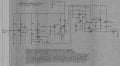
This is a circuit I designed and built couple months back.
I wanted to use it as a proof of concept, of how I could design a PWM circuit to drive a battery drill at extreme low speeds and plenty of torque.
Again this is not a nessasary circuit I need to have, but rather just an exercise in learning how to design transistor circuits.
 

Attachments

jpanhalt

Joined Jan 18, 2008
11,087
The IRF610 is N-channel. How are you boosting the gate voltage to get it to turn on fully in a high-side configuration as you have designed?

Perhaps, since this is not a finished project, it should be moved to to the Projects Forum.

John
 

Thread Starter

hobbyist

Joined Aug 10, 2008
892
The IRF610 is N-channel. How are you boosting the gate voltage to get it to turn on fully in a high-side configuration as you have designed?

Perhaps, since this is not a finished project, it should be moved to to the Projects Forum.

John
Hi John,

I'm not sure it was fully on.

If I remember correctly I think I looked at the waveform at the source terminal and not directly across the motor.

And when I was getting the square wave the smallest pulse width, started at about maybe 25% duty cycle, then as I stalled the motor I was able to see the pulse width expand about another 10 to 20 % more.

With this setup I could not get above 50% duty cycle.
probably because lack of full gate voltage.

I hardly ever worked with mosfets before so this was my first attempt at using them in a working circuit.
But again this circuit is a experiment to see if I understood PWM with torque controle enough to be able to make a workable proof of concept project.

I tried to put the mosfet in the low side of the load, but I had a hard time getting the linear response, that I am able to get with the mosfet on the high side. When it comes to increase torque voltage.

When the mosfet is on the low side of the load the motor when stalled, would jump to full on. There was no linear response.

Not using PWM, but testing the torque controle circuit, I could watch the voltage increase at the source terminal, when ever a slightest amount of pressure was put on the motor shaft, and I could hold it at a specific output voltage just by maintaining the same amount of load to the motor, and as I increase the load the voltage varied in linear manner.

When I say load, I'm saying putting pressure on the motor shaft, but it responds linearly with increase or decrease in load.

That's why I use this configuration.

Thanks...
 
Top