Facebook
 Google
 GitHub
 Linkedin
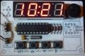
I'd like to present a relatively simple 4-digit 99 minute timer project. The low parts count design is a result of experiments with some very bright miniature 4-digit displays available from Sparkfun that come in red, green, yellow, white (all $1.95), and blue ($2.50) colors.

In addition to the Digital 99 Minute Timer presented here, the circuit design, with minor modifications, might support several other projects, including, but not limited to;
() Digital Voltage Monitor
() Digital Thermometer
() Digital Thermostat
() Repeating On/Off Interval Timer
() Digital Alarm Clock
() Digital Clock/Calendar/Alarm/Timer
() Digital Stopwatch
() Digital RPM Indicator
Requirements
You'll need a programmer of some sort to program the PIC16F1828 device and you'll also need a regulated 5 Vdc power source to power the circuit. You'll also need a simple transistor, opti-isolator, SSR (Solid State Relay IC), or similar driver circuit which will take its input from the active high output signal on the RA2 pin. The output circuit you choose depends on what you need to drive (relay, etc.)

Hardware
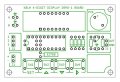
The wiring diagram shows several components that are not required for the 99 Minute Timer application. Specifically, you don't need to install the crystal and capacitors in the oscillator block and you don't need to install the two discrete 'A' and 'B' LEDs for this particular project.
The little 4-digit displays are so bright that I decided to drive them one segment at a time (1/32nd duty cycle) directly from the PIC16F1828 I/O pins (no column/digit driver transistors). Due to the low duty cycle, I omitted current limiting resistors for the cathode segments, relying instead on 250 ohms combined RDS(ON) resistance of the I/O pin FET drivers inside of the PIC (about 150 ohms for a high-side 'sourcing' FET driver and about 100 ohms for a low-side 'sinking' FET driver).
While the circuit supports any color display, please note that the red, green, and yellow displays have a VF of 2.1 volts, while the white display is 3.1 volts, and the blue display is 3.4 volts. This means that while the blue and white displays are bright and easily visible in a brightly lighted room, the red, green, and yellow displays are a bit brighter. I hope to add a software PWM brightness control to a future version of the program.
Parts List
Software
The attached HEX file can be used directly with a PICKIT2 or PICKIT3 to program the PIC16F1828 device. The program was written using the free/lite version of BoostC from Sourceboost. While you can use the Sourceboost IDE (Integrated Development Environment), I chose the option to install BoostC into the MPLAB IDE. The program uses packed BCD "minutes" and "seconds" variables and the code to increment and decrement those variables may look a little strange to some programmers.
Operation
The <SET> switch is used to toggle between "set" and "run" modes. Press <SET> to enter "set" mode and the "minutes" display group will flash at a 2-Hz rate. While in "set" mode the <Rt> arrow key is used to toggle between the "minutes" and the "seconds" display group and the <Up> and <Dn> arrow switches are used to increment or decrement the value of the current flashing display group. The "minutes" display group will rollover from 99 to 0 or from 0 to 99 and the "seconds" display group will rollover from 59 to 0 or from 0 to 59. The <Up> and <Dn> arrow switches will repeat when held down. Press <SET> again to exit "set" mode and enter "run" mode (display stops flashing). In "run" mode you press the <Rt> arrow switch to start or stop the Timer. An active high signal is available on the RA2 pin when the Timer is running. While the Timer is running and counting down, the <SET> switch, the <Up> switch, and the <Dn> switch are disabled. Those switches are still sampled and debounced in the interrupt service routine and you'll still hear a "new press" beep when you press one of them but they're ignored and cleared by the logic in the program. If you have any questions, please ask...
In addition to the Digital 99 Minute Timer presented here, the circuit design, with minor modifications, might support several other projects, including, but not limited to;
() Digital Voltage Monitor
() Digital Thermometer
() Digital Thermostat
() Repeating On/Off Interval Timer
() Digital Alarm Clock
() Digital Clock/Calendar/Alarm/Timer
() Digital Stopwatch
() Digital RPM Indicator
Requirements
You'll need a programmer of some sort to program the PIC16F1828 device and you'll also need a regulated 5 Vdc power source to power the circuit. You'll also need a simple transistor, opti-isolator, SSR (Solid State Relay IC), or similar driver circuit which will take its input from the active high output signal on the RA2 pin. The output circuit you choose depends on what you need to drive (relay, etc.)
Hardware
The wiring diagram shows several components that are not required for the 99 Minute Timer application. Specifically, you don't need to install the crystal and capacitors in the oscillator block and you don't need to install the two discrete 'A' and 'B' LEDs for this particular project.
The little 4-digit displays are so bright that I decided to drive them one segment at a time (1/32nd duty cycle) directly from the PIC16F1828 I/O pins (no column/digit driver transistors). Due to the low duty cycle, I omitted current limiting resistors for the cathode segments, relying instead on 250 ohms combined RDS(ON) resistance of the I/O pin FET drivers inside of the PIC (about 150 ohms for a high-side 'sourcing' FET driver and about 100 ohms for a low-side 'sinking' FET driver).
While the circuit supports any color display, please note that the red, green, and yellow displays have a VF of 2.1 volts, while the white display is 3.1 volts, and the blue display is 3.4 volts. This means that while the blue and white displays are bright and easily visible in a brightly lighted room, the red, green, and yellow displays are a bit brighter. I hope to add a software PWM brightness control to a future version of the program.
Parts List
Rich (BB code):
1 ea. PIC16F1828-I/P (DIP package)
1 ea. 0.1-uf (100nf) ceramic capacitor
1 ea. 10 kOhm, 1/8th watt carbon film resistor
4 ea. 1N914 or 1N4148 silicon switching diode
1 ea. Sparkfun COM-09481 Blue Common Anode 4-Digit Display
4 ea. generic momentary contact switch
1 ea. Soberton GT111P Piezo Speaker
Misc. sockets, connectors, prototype circuit boardThe attached HEX file can be used directly with a PICKIT2 or PICKIT3 to program the PIC16F1828 device. The program was written using the free/lite version of BoostC from Sourceboost. While you can use the Sourceboost IDE (Integrated Development Environment), I chose the option to install BoostC into the MPLAB IDE. The program uses packed BCD "minutes" and "seconds" variables and the code to increment and decrement those variables may look a little strange to some programmers.
Operation
The <SET> switch is used to toggle between "set" and "run" modes. Press <SET> to enter "set" mode and the "minutes" display group will flash at a 2-Hz rate. While in "set" mode the <Rt> arrow key is used to toggle between the "minutes" and the "seconds" display group and the <Up> and <Dn> arrow switches are used to increment or decrement the value of the current flashing display group. The "minutes" display group will rollover from 99 to 0 or from 0 to 99 and the "seconds" display group will rollover from 59 to 0 or from 0 to 59. The <Up> and <Dn> arrow switches will repeat when held down. Press <SET> again to exit "set" mode and enter "run" mode (display stops flashing). In "run" mode you press the <Rt> arrow switch to start or stop the Timer. An active high signal is available on the RA2 pin when the Timer is running. While the Timer is running and counting down, the <SET> switch, the <Up> switch, and the <Dn> switch are disabled. Those switches are still sampled and debounced in the interrupt service routine and you'll still hear a "new press" beep when you press one of them but they're ignored and cleared by the logic in the program. If you have any questions, please ask...
Attachments
-
 77.7 KB Views: 2,271
 -
 61.5 KB Views: 261
 -
2 KB Views: 185
-
14.4 KB Views: 283
-
 107.4 KB Views: 2,230
 -
 182.2 KB Views: 221
Last edited: