 Facebook
 Google
 GitHub
 Linkedin
Hi
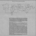
This is a circuit I made long time ago and I wrote a paper about it.
This is a circuit I made long time ago and I wrote a paper about it.
Attachments
-
 289.2 KB Views: 423
Last edited by a moderator:


