 Facebook
 Google
 GitHub
 Linkedin
Project: 1.5V White LED Driver
By: John S Rohrer
A result of many attempts over several years, this circuit alternately drives two white LEDs using a single alkaline cell (1.1 to 1.6 volts). A typical alkaline D cell will drive these two LEDs for over 200 hours while producing 10 candelas of light from the two LEDs combined. (Plenty to see in the dark.)
The complete utility light assembly adds about 25% to the volume of a D cell itself, and has survived repeated physical torture tests.
This design is for a small flashlight that is reliable, manufacturable on a small scale, and which provides more than 200 hours of light from a single alkaline D cell. Such a light would be suitable for emergency situations. The D cell is chosen because it is available worldwide. Alkaline D cell voltage starts at 1.6 volts (V), with most of the energy expended at 1.2 V, and virtually no energy left at 1.0 V. For maximum life, this design will function down to 1.0 V.
White LEDs are more efficient than incandescent bulbs, more vibration resistant, and last much longer. A downside is the loss of the pleasing visual spectrum of an incandescent bulb. LEDs are also chosen because the 5 millimeter (mM) or T-1 3/4 package is available with a narrow (15 degree) viewing angle, eliminating the need for focusing reflectors or lens. A 15 degree viewing angle illuminates a 1 foot diameter area 6 feet away from the LED. This may seem small, but a beam covering a 2 foot area would be only 1/4 as bright. So the choice is concentrated brightness.
Given that LEDs become less efficient at higher currents, the best way to power an LED would be continuous direct current at about 60% of the LED maximum current. But the conversion from 1.5 V to 3.5 V requires oscillation or pulsing. The pulsed drive should have as large a duty cycle as possible to reduce the peak currents versus the average current in the LED, and thus maintain LED efficiency.
There should be no perceptible flickering in the light output. So the pulse rate should be well above visual sensitivity, which is about 60 times per second.
Some transformers and ceramic capacitors are microphonic, converting electrical signals into audible ones. Since noise is not desirable, the pulsing frequency also should be above the human audible range, which is roughly 20,000 times per second (Hz).
An easily buildable flashlight implies common mechanical parts, with no machining.
REASONING
Altho’ white LEDs require about 3.5 V to turn on, they are easily destroyed if the voltage is forced higher. In the simplest circuits that can do the job, a single inductor stores energy in a magnetic field. The inductor energy is released as current to drive the LED, with the voltage determined by the LED forward drop. The time required to store the energy at the lower cell voltage is greater than the time to release it at the higher LED voltage; specifically, the storage time divided by discharge time is proportional to the LED voltage divided by input (cell) voltage. This 3:1 to 4:1 ratio can be reduced by placing the inductor step-up voltage on top of the cell voltage, dropping the ratio to 2:1 to 3:1, but even this is less than 50% duty cycle for the LED. The problem can be eased by a tapped inductor (transformer), which decreases the time required to store the magnetic energy. Such designs are common, yielding a simple circuit that supplies the needed current during each charge-discharge cycle.
The tapped inductor can also be employed as a transformer to provide voltage to drive an LED while magnetic energy is being stored in the transformer magnetic field. Thus LEDs can be driven during energy storage and during energy release. But the transformer output voltage is of opposite polarity for energy storage versus energy release. Using a single LED implies diodes or transistors to steer the alternating current to it, but these would waste power. Two LEDs paralleled in opposite directions across the transformer output is more efficient. One LED would be on while the other is off.
If the transformer turns ratio is 4 to 1, then less than 1 volt can produce enough voltage to drive an LED during energy storage. This means that the LED powered by transformer action during energy storage will produce light for cell voltage down below 1 V.
IMPLEMENTATION
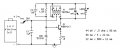
The following schematic is the result of several "Not that way!” experiences. For instance, transformer T1 is relatively expensive; however, when the assembly time and effort to produce a replacement are considered, it is a bargain.
View attachment 149212

Circuit Operation
When switch SW1 is turned on, DC current flows thru T1 winding 2-1-4-6 and R3 to the parallel combination of DZ1 and Q1 base. In other designs, the current increases until limited by transformer saturation. This design has a specific current limit implemented by zener diode DZ1, transistor Q1, and the paralleled emitter resistance R1-R2. Forward-biased DZ1 has a higher voltage drop than the Vbe of Q1 because the junction doping for zener diodes raises the forward voltage drop over that of a comparable transistor base-emitter junction. This voltage difference can be increased if a small area DZ1 is used with a large area Q1. The difference can be 40 to 60 millivolts (mV). This difference causes most of the R3 current to flow into the base of Q1, turning it on.
As Q1 turns on, the voltage across winding 2-3 of T1 increases. Transformer action produces four times that voltage across winding 3-1-4-6 and thus the LEDs. This drives Q1 on even harder thru R3 (and C2, which speeds the transition), until LED1 is turned on. Now there is a constant voltage momentarily across winding 2-3 while Q1 is saturated, and the current thru 2-3 increases at a rate determined by T1's inductance. As the current increases, the voltage drop across R1-R2 increases until that voltage plus Q1 base-emitter voltage begins to equal the drop across DZ1. This diverts more current into DZ1, limiting Q2 current. Measurements with an FMMT617 transistor, an R1-R2 emitter resistance of 0.5 ohm, and a FLZ5V1A zener diode yield a Q2 current limit of about 90 mA. This implies that the peak voltage across DZ1 minus the voltage across Vbe1 is about 90 mV / 0.5 ohm = 45 mV.
With a 1 to 4 reduction in current due to transformer action, the LED1 peak current is 23 mA. Each LED is on for only part of a cycle, with the current ramping approximately linearly (constant voltage) from zero to peak and back to zero during the "on" time. So a 23 mA peak current with linear current ramping averaged over a full cycle (0-23-0 mA) corresponds to an average current of about 6 mA per LED. The typical operating current of a 5 mM white LED is 10 mA.
The DZ1 current limit stabilizes the light output versus cell voltage. However, the time to store this energy each cycle varies with the cell voltage, so there is some brightness variation versus voltage due to this. But there is less variation than with no current limit. The current limit also prevents transformer saturation, which would lower efficiency.
As the current limit is reached, the "rate of current increase" thru T1 becomes zero, so the voltage across pins 3-6 drops to zero, as expressed in the equation dI/dT = V/L. This shuts Q1 off, and the magnetic energy stored in the transformer produces a negative output voltage across pins 3-6, which powers LED2 until the energy stored in T1 inductance is depleted. Then R3 supplies base current to Q1 again, and the cycle starts over.
When the cell voltage drops below 3.6 V / 4 = 0.9 volts, there is insufficient voltage to drive LED1, but the transformer still delivers energy to LED2 on the second part of the cycle during the magnetic field discharge. This provides an end-of-battery-life indication as LED1 goes out but LED2 stays on.
If Q1 is oscillating, it will continue to do so until the cell voltage drops below 0.2 volt because transformer T1 steps that up to 0.8 volt, which is enough to turn Q1 on to start a new cycle. And current is delivered to LED1 [Edit was LED2] each cycle, altho' it dims considerably as the battery voltage drops. And because the cell will usually recover from 0.2 volt to above 0.7 volt with a little rest, it will produce some light from a cell that would be totally dead in any other device.
Note: A transformer's ability to hold a pulsed output voltage constant versus time is measured by its "volt-microsecond" capability. A transformer with a 50 V-uS rating can hold 4 volts for: 50 V-uS / 4 V = 12.5 uS, which is the half-period of the ~ 40 KHz operating frequency.
C1 provides a low impedance across the D cell at higher frequencies.
Prototypes have been built using a commonly available (Eagle Industries) plastic D cell battery holder with the printed circuit board mounted to the battery holder. The shape of this assembly allows for convenient positioning of the flashlight when it is set down, and it fits nicely in the hand. The assembly does not break despite multiple 3 foot drops onto concrete.
The circuit draws about 80 mA at 1.6 V and 35 mA at 1.0 V. A D cell typically stores 12 ampere-hours (AH), yielding about 200 hours of life. Eight hours use a day means 25 days of life.
The brightness at 1.6 V decreases to about one-half at 1.2 V.
Costs
In quantities of 100, the circuit board runs about $4.00, the switch $3.00, the transformer $2.70, the battery holder $1.00, with miscellaneous parts adding another $3.00, for a parts total of $13.70.
With this, all design goals have been met.


Above: Component side copper which has all of the circuit connections.
-------------------------------------
I note an error in the schematic. The original design used two 1 ohm resistors in parallel (R1 and R2) because 1 ohm resistors were easier to obtain than 0.5 ohm resistors. But today 0.5 ohm resistors are commonly available, and only an R1 of 0.5 ohm is needed, not any R2. See attached schematic.

By: John S Rohrer
A result of many attempts over several years, this circuit alternately drives two white LEDs using a single alkaline cell (1.1 to 1.6 volts). A typical alkaline D cell will drive these two LEDs for over 200 hours while producing 10 candelas of light from the two LEDs combined. (Plenty to see in the dark.)
The complete utility light assembly adds about 25% to the volume of a D cell itself, and has survived repeated physical torture tests.
This design is for a small flashlight that is reliable, manufacturable on a small scale, and which provides more than 200 hours of light from a single alkaline D cell. Such a light would be suitable for emergency situations. The D cell is chosen because it is available worldwide. Alkaline D cell voltage starts at 1.6 volts (V), with most of the energy expended at 1.2 V, and virtually no energy left at 1.0 V. For maximum life, this design will function down to 1.0 V.
White LEDs are more efficient than incandescent bulbs, more vibration resistant, and last much longer. A downside is the loss of the pleasing visual spectrum of an incandescent bulb. LEDs are also chosen because the 5 millimeter (mM) or T-1 3/4 package is available with a narrow (15 degree) viewing angle, eliminating the need for focusing reflectors or lens. A 15 degree viewing angle illuminates a 1 foot diameter area 6 feet away from the LED. This may seem small, but a beam covering a 2 foot area would be only 1/4 as bright. So the choice is concentrated brightness.
Given that LEDs become less efficient at higher currents, the best way to power an LED would be continuous direct current at about 60% of the LED maximum current. But the conversion from 1.5 V to 3.5 V requires oscillation or pulsing. The pulsed drive should have as large a duty cycle as possible to reduce the peak currents versus the average current in the LED, and thus maintain LED efficiency.
There should be no perceptible flickering in the light output. So the pulse rate should be well above visual sensitivity, which is about 60 times per second.
Some transformers and ceramic capacitors are microphonic, converting electrical signals into audible ones. Since noise is not desirable, the pulsing frequency also should be above the human audible range, which is roughly 20,000 times per second (Hz).
An easily buildable flashlight implies common mechanical parts, with no machining.
REASONING
Altho’ white LEDs require about 3.5 V to turn on, they are easily destroyed if the voltage is forced higher. In the simplest circuits that can do the job, a single inductor stores energy in a magnetic field. The inductor energy is released as current to drive the LED, with the voltage determined by the LED forward drop. The time required to store the energy at the lower cell voltage is greater than the time to release it at the higher LED voltage; specifically, the storage time divided by discharge time is proportional to the LED voltage divided by input (cell) voltage. This 3:1 to 4:1 ratio can be reduced by placing the inductor step-up voltage on top of the cell voltage, dropping the ratio to 2:1 to 3:1, but even this is less than 50% duty cycle for the LED. The problem can be eased by a tapped inductor (transformer), which decreases the time required to store the magnetic energy. Such designs are common, yielding a simple circuit that supplies the needed current during each charge-discharge cycle.
The tapped inductor can also be employed as a transformer to provide voltage to drive an LED while magnetic energy is being stored in the transformer magnetic field. Thus LEDs can be driven during energy storage and during energy release. But the transformer output voltage is of opposite polarity for energy storage versus energy release. Using a single LED implies diodes or transistors to steer the alternating current to it, but these would waste power. Two LEDs paralleled in opposite directions across the transformer output is more efficient. One LED would be on while the other is off.
If the transformer turns ratio is 4 to 1, then less than 1 volt can produce enough voltage to drive an LED during energy storage. This means that the LED powered by transformer action during energy storage will produce light for cell voltage down below 1 V.
IMPLEMENTATION
The following schematic is the result of several "Not that way!” experiences. For instance, transformer T1 is relatively expensive; however, when the assembly time and effort to produce a replacement are considered, it is a bargain.
View attachment 149212
Circuit Operation
When switch SW1 is turned on, DC current flows thru T1 winding 2-1-4-6 and R3 to the parallel combination of DZ1 and Q1 base. In other designs, the current increases until limited by transformer saturation. This design has a specific current limit implemented by zener diode DZ1, transistor Q1, and the paralleled emitter resistance R1-R2. Forward-biased DZ1 has a higher voltage drop than the Vbe of Q1 because the junction doping for zener diodes raises the forward voltage drop over that of a comparable transistor base-emitter junction. This voltage difference can be increased if a small area DZ1 is used with a large area Q1. The difference can be 40 to 60 millivolts (mV). This difference causes most of the R3 current to flow into the base of Q1, turning it on.
As Q1 turns on, the voltage across winding 2-3 of T1 increases. Transformer action produces four times that voltage across winding 3-1-4-6 and thus the LEDs. This drives Q1 on even harder thru R3 (and C2, which speeds the transition), until LED1 is turned on. Now there is a constant voltage momentarily across winding 2-3 while Q1 is saturated, and the current thru 2-3 increases at a rate determined by T1's inductance. As the current increases, the voltage drop across R1-R2 increases until that voltage plus Q1 base-emitter voltage begins to equal the drop across DZ1. This diverts more current into DZ1, limiting Q2 current. Measurements with an FMMT617 transistor, an R1-R2 emitter resistance of 0.5 ohm, and a FLZ5V1A zener diode yield a Q2 current limit of about 90 mA. This implies that the peak voltage across DZ1 minus the voltage across Vbe1 is about 90 mV / 0.5 ohm = 45 mV.
With a 1 to 4 reduction in current due to transformer action, the LED1 peak current is 23 mA. Each LED is on for only part of a cycle, with the current ramping approximately linearly (constant voltage) from zero to peak and back to zero during the "on" time. So a 23 mA peak current with linear current ramping averaged over a full cycle (0-23-0 mA) corresponds to an average current of about 6 mA per LED. The typical operating current of a 5 mM white LED is 10 mA.
The DZ1 current limit stabilizes the light output versus cell voltage. However, the time to store this energy each cycle varies with the cell voltage, so there is some brightness variation versus voltage due to this. But there is less variation than with no current limit. The current limit also prevents transformer saturation, which would lower efficiency.
As the current limit is reached, the "rate of current increase" thru T1 becomes zero, so the voltage across pins 3-6 drops to zero, as expressed in the equation dI/dT = V/L. This shuts Q1 off, and the magnetic energy stored in the transformer produces a negative output voltage across pins 3-6, which powers LED2 until the energy stored in T1 inductance is depleted. Then R3 supplies base current to Q1 again, and the cycle starts over.
When the cell voltage drops below 3.6 V / 4 = 0.9 volts, there is insufficient voltage to drive LED1, but the transformer still delivers energy to LED2 on the second part of the cycle during the magnetic field discharge. This provides an end-of-battery-life indication as LED1 goes out but LED2 stays on.
If Q1 is oscillating, it will continue to do so until the cell voltage drops below 0.2 volt because transformer T1 steps that up to 0.8 volt, which is enough to turn Q1 on to start a new cycle. And current is delivered to LED1 [Edit was LED2] each cycle, altho' it dims considerably as the battery voltage drops. And because the cell will usually recover from 0.2 volt to above 0.7 volt with a little rest, it will produce some light from a cell that would be totally dead in any other device.
Note: A transformer's ability to hold a pulsed output voltage constant versus time is measured by its "volt-microsecond" capability. A transformer with a 50 V-uS rating can hold 4 volts for: 50 V-uS / 4 V = 12.5 uS, which is the half-period of the ~ 40 KHz operating frequency.
C1 provides a low impedance across the D cell at higher frequencies.
Prototypes have been built using a commonly available (Eagle Industries) plastic D cell battery holder with the printed circuit board mounted to the battery holder. The shape of this assembly allows for convenient positioning of the flashlight when it is set down, and it fits nicely in the hand. The assembly does not break despite multiple 3 foot drops onto concrete.
The circuit draws about 80 mA at 1.6 V and 35 mA at 1.0 V. A D cell typically stores 12 ampere-hours (AH), yielding about 200 hours of life. Eight hours use a day means 25 days of life.
The brightness at 1.6 V decreases to about one-half at 1.2 V.
Costs
In quantities of 100, the circuit board runs about $4.00, the switch $3.00, the transformer $2.70, the battery holder $1.00, with miscellaneous parts adding another $3.00, for a parts total of $13.70.
With this, all design goals have been met.
Above: Component side copper which has all of the circuit connections.
-------------------------------------
I note an error in the schematic. The original design used two 1 ohm resistors in parallel (R1 and R2) because 1 ohm resistors were easier to obtain than 0.5 ohm resistors. But today 0.5 ohm resistors are commonly available, and only an R1 of 0.5 ohm is needed, not any R2. See attached schematic.
Attachments
-
886 bytes Views: 24
-
 25.4 KB Views: 28
Last edited by a moderator:


