Program PIC16F876A with PICkit3

Thread Starter

James_2012

Joined May 24, 2012
5
Greetings All,

Someone please help me troubleshoot what the issue is with my code and my PIC.

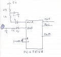
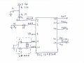
I'm using MPlab X IDE 1.10 and PICkit3 trying to burn a simple code to turn on a LED using the I/O ports. The PICkit3 supply the power to the target board which in ICSP program mode with PIN1 connected to a 22KΩ pull-up resistor connected to Vpp. PIN1 also connected to a capacitor across ground.

1)The code compiled with a warming "Found directive in column 1. (__CONFIG)" which i think its alright.
2)It also programed without any issues "Programming...
Programming/Verify complete"
3) The LED is connected correctly and the board has power Vpp = 4.8V supplied by PICkit3.

PROBLEM::confused:
1) Nothing happen after program is complete, i measured the voltage on all the pins at porta i got 0V

Below is my complete code in assembly.
******************************************************

#include P16F876A.INC
#define XTAL FREQ 20MHZ ; using 20Mhz ceramic crystal oscillator.
__CONFIG (_XT_OSC & _WDT_OFF & _PWRTE_OFF & _BOREN_OFF & _LVP_OFF & _CPD_OFF & _WRT_OFF & _CP_OFF );

ORG 0x00
MOVLW 0x7
MOVWF ADCON1
MOVLW 0x00
MOVWF TRISA ;Set PortA output
MOVLW 0x00
MOVWF PORTA ;Clear PortA
HERE
MOVLW 0xFF ;Set all portA high
MOVWF PORTA
GOTO HERE
END
****************************************************************

Please help

Thank you all in advance!
 

t06afre

Joined May 11, 2009
5,934
Have you checked the level on the MCLR pin? Also I think in your case. You should configure for HS oscillator. Looking at your code. I can not see any setting of the data memory banking bits. That is the main culprit I think Read section 2.2 in the datasheet. Try This
Rich (BB code):
#include P16F876A.INC
#define XTAL FREQ 20MHZ ; using 20Mhz ceramic crystal oscillator. 
__CONFIG (_XT_OSC & _WDT_OFF & _PWRTE_OFF & _BOREN_OFF & _LVP_OFF & _CPD_OFF & _WRT_OFF & _CP_OFF );

ORG 0x00
MOVLW 0x7
banksel ADCON1
MOVWF ADCON1
MOVLW 0x00
MOVWF TRISA ;Set PortA output
banksel PORTA
MOVLW 0x00
MOVWF PORTA ;Clear PortA
HERE
MOVLW 0xFF ;Set all portA high
MOVWF PORTA
GOTO HERE
END
 

Thread Starter

James_2012

Joined May 24, 2012
5
Thank you t06afre,

Voltage level on the MCLR pin is about 4.5V. I tried what you recommended but still nothing happening.

James_2012
 

Thread Starter

James_2012

Joined May 24, 2012
5
Thank you t06afre! it works now.
after i added the banksel and burned to the PIC i notice my led flashes when i unplugged the PICkit3 so I i unplugged the PICkit3 power supply and and use an external power source and the led lid up like it should (probably got to do with the whole thing in a breadboard). And off when i burn a different program.

Haven't figure out how to make it flash yet in assembly language.

Any way attached is my schematic and the code below. hope it will be helpful to others in the future.
*********************************************************************
#include P16F876A.INC
#define XTAL FREQ 20MHZ ; using 20Mhz ceramic crystal oscillator.
__CONFIG (_XT_OSC & _WDT_OFF & _PWRTE_OFF & _BOREN_OFF & _LVP_OFF & _CPD_OFF & _WRT_OFF & _CP_OFF );

ORG 0x00
MOVLW 0x6
banksel ADCON1
MOVWF ADCON1
MOVLW 0x00
MOVWF TRISA ;Set PortA output
banksel PORTA
MOVLW 0x00
MOVWF PORTA ;Clear PortA
HERE
MOVLW 0xFF
MOVWF PORTA
GOTO HERE
END

***********************************************************************

Again Thank You t06afree for your help.:):)
 

Attachments

coldpenguin

Joined Apr 18, 2010
165
Might be a stupid question, I don't use the PickKit, I use the ICD2.

When I burn a program using MpLAB, I then have to go to Programmer->Release from Reset

This clears the MCLR pin, and the PIC runs.

Similarly, unplugging the PicKit would do the same thing..... (assuming it isn't an oscillator issue). I was kinda expecting two capacitors either side of the crystal (10-22nf is what I use) connected to ground.
 

t06afre

Joined May 11, 2009
5,934
Might be a stupid question, I don't use the PickKit, I use the ICD2.

When I burn a program using MpLAB, I then have to go to Programmer->Release from Reset

This clears the MCLR pin, and the PIC runs.

Similarly, unplugging the PicKit would do the same thing..... (assuming it isn't an oscillator issue). I was kinda expecting two capacitors either side of the crystal (10-22nf is what I use) connected to ground.
That sounds correct. I use newer PICs. And they have an option to disable the MCLR function and the MCLR pin will be normal input pin. In my projects I always prefer to do this.
 

Thread Starter

James_2012

Joined May 24, 2012
5
I was kinda expecting two capacitors either side of the crystal (10-22nf is what I use) connected to ground.
You're correct coldpenguin, i used a 20 MHZ ceramic crystal with an internal capacitors.

@ MrChips - no it doesn't flash yet, it only turns on the LED. I'm not that familiar with assembly, but from what i read it doesn't have a delay function.:confused:
 

nerdegutta

Joined Dec 15, 2009
2,689
Ref the pencil drawn schematic.

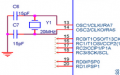
Shouldn't the crystal be connected to GND with some caps? Like this:

Pin name and number differ. Just for explanation of the crystal/cap wiring.

EDIT:
Got distracted before I hit the submit button....
 

Attachments

Last edited:

tracecom

Joined Apr 16, 2010
3,944
Ref the pencil drawn schematic.

Shouldn't the crystal be connected to GND with some caps? Like this:

Pin name and number differ. Just for explanation of the crystal/cap wiring.

EDIT:
Got distracted before I hit the submit button....
You are correct; the data sheet calls for small caps as you have them drawn (often 22pF), but I have found (by accident) that the crystals will sometimes oscillate without the caps.
 

t06afre

Joined May 11, 2009
5,934
Ref the pencil drawn schematic.

Shouldn't the crystal be connected to GND with some caps? Like this:

Pin name and number differ. Just for explanation of the crystal/cap wiring.

EDIT:
Got distracted before I hit the submit button....
In this case the OP use a resonator. Which is kind of poor mans crystal. Some these come in a 3 pin package with internal caps. Just like the OP use. If you go to your component pusher. And search for resonator and select those with 3 pins. You will get a selction of the latter.
You can also take a look here http://www.oscilent.com/catalog/Category/ceramic_resonator.htm
 

coldpenguin

Joined Apr 18, 2010
165
That sounds correct. I use newer PICs. And they have an option to disable the MCLR function and the MCLR pin will be normal input pin. In my projects I always prefer to do this.
I don't see MCLRE being disabled in the _Config bits......, looking through the .inc, _LVP_OFF makes MCLRE be used

You're correct coldpenguin, i used a 20 MHZ ceramic crystal with an internal capacitors.

@ MrChips - no it doesn't flash yet, it only turns on the LED. I'm not that familiar with assembly, but from what i read it doesn't have a delay function.:confused:
No real delay, you just hang around doing nothing.

Add around 500k
Rich (BB code):
NOP
just before your goto HERE.
(Sorry, can't remember how to count in ASM)
 

coldpenguin

Joined Apr 18, 2010
165
That is because the chip the OP use. Do not offer that option
OK, sorry, I have always used the MCLRE and am not very good at interpereting the .inc files.

My p16f876a.inc has the following
Rich (BB code):
;==========================================================================
;
;       Configuration Bits
;
;   NAME            Address
;   CONFIG            2007h
;
;==========================================================================

; The following is an assignment of address values for all of the
; configuration registers for the purpose of table reads
_CONFIG          EQU  H'2007'

;----- CONFIG Options --------------------------------------------------
_FOSC_LP             EQU  H'3FFC'    ; LP oscillator
_LP_OSC              EQU  H'3FFC'    ; LP oscillator
_FOSC_XT             EQU  H'3FFD'    ; XT oscillator
_XT_OSC              EQU  H'3FFD'    ; XT oscillator
_FOSC_HS             EQU  H'3FFE'    ; HS oscillator
_HS_OSC              EQU  H'3FFE'    ; HS oscillator
_FOSC_EXTRC          EQU  H'3FFF'    ; RC oscillator
_RC_OSC              EQU  H'3FFF'    ; RC oscillator

_WDTE_OFF            EQU  H'3FFB'    ; WDT disabled
_WDT_OFF             EQU  H'3FFB'    ; WDT disabled
_WDTE_ON             EQU  H'3FFF'    ; WDT enabled
_WDT_ON              EQU  H'3FFF'    ; WDT enabled

_PWRTE_ON            EQU  H'3FF7'    ; PWRT enabled
_PWRTE_OFF           EQU  H'3FFF'    ; PWRT disabled

_BOREN_OFF           EQU  H'3FBF'    ; BOR disabled
_BODEN_OFF           EQU  H'3FBF'    ; BOR disabled
_BOREN_ON            EQU  H'3FFF'    ; BOR enabled
_BODEN_ON            EQU  H'3FFF'    ; BOR enabled

_LVP_OFF             EQU  H'3F7F'    ; RB3 is digital I/O, HV on MCLR must be used for programming
_LVP_ON              EQU  H'3FFF'    ; RB3/PGM pin has PGM function; low-voltage programming enabled
Which made me think, given the comment that MCLR was enabled 'cos the _config in the code had _LVP_OFF (and would otherwise be disabled). Confusing.
 

maxpower097

Joined Feb 20, 2009
816
Try you project in MPLAB 8. I recently had to do some work on a PIC16LF877A and was all stoked about the mplabX and its features. Well with the PK3 or what ever it just wasn't happening. I couldn't get jack or S#$^ to run right. I switched back to MPlab8 and bam no code modification and it ran perfectly. Also every once and a while the PK3 won't detect the chip right. Just override it and program it anyways and it will program and verify. Its one of those errors saying (Device ID mismatch 0X00 was received when 0x08 was expected) Sometimes it follows the code from computer to computer, sometimes it resets and works right. So you got bugs in the PK3 for the PIC16 and bugs in MPlabX. So I would try mplab 8 and re-evaluate your sitcheation.
 
Top