Problems solving this resistor circuit problem

Thread Starter

MarceUni

Joined May 6, 2018
5
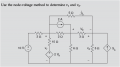
Hello everyone, I am trying to solve this circuit to find V1 and V2.

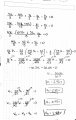
I just start selecting the 3 nodes and I have the next equations (using the currents):

1. Node A
(10-V1)/3 = 2 + (V1-V2)/5 + (V1-V3)/2 + (V1-2Vb)/10

2. Node B
2 + (V1-V3)/2 = V3/6 + Vb/3 with Vb = V3 - V2

3. Node C
ia + Vb/3 + 3ia = V2/5

At the end the voltages that I found are V1=2.92V V3=2.83V V2=0.95V and Vb=1.88V

It is correct the procedure? Are the voltages rigth?

Thanks in advance
 

Attachments

WBahn

Joined Mar 31, 2012
30,077
If you are going to talk about Node A (or B or C), it would be very helpful to have them identified on your schematic instead of making people guess. Similarly, you use V3 but nowhere define what it is. Annotate your schematic with ALL voltages and currents that you use so that people (including yourself) can check your work to be sure it is consistent with the definitions you made.

You need to learn to properly track your units.

Once you have a proposed solution, you need to learn to check it. Using the proposed answers, determine the currents at each node and see if KCL is satisfied and determine the outputs of the dependent supplies and see if they agree with the control signals.
 

Thread Starter

MarceUni

Joined May 6, 2018
5
If you are going to talk about Node A (or B or C), it would be very helpful to have them identified on your schematic instead of making people guess. Similarly, you use V3 but nowhere define what it is. Annotate your schematic with ALL voltages and currents that you use so that people (including yourself) can check your work to be sure it is consistent with the definitions you made.

You need to learn to properly track your units.

Once you have a proposed solution, you need to learn to check it. Using the proposed answers, determine the currents at each node and see if KCL is satisfied and determine the outputs of the dependent supplies and see if they agree with the control signals.

Hello WBahn,

Thanks for the reply, and you are rigth, I forgot to upload the circuit image with the details, as you can see in this post everything is in there.

Thanks
 

Attachments

Hymie

Joined Mar 30, 2018
1,284
Hello WBahn,

Thanks for the reply, and you are rigth, I forgot to upload the circuit image with the details, as you can see in this post everything is in there.

Thanks
I don’t understand the circuit, it appears that the 2 ohm resistor has a short circuit across it, through which is flowing 2A. Or is that how a flow of 2A through a resistor is indicated?
 

WBahn

Joined Mar 31, 2012
30,077
I don’t understand the circuit, it appears that the 2 ohm resistor has a short circuit across it, through which is flowing 2A. Or is that how a flow of 2A through a resistor is indicated?
It's a 2 A current source. Just like a ideal voltage source produces whatever current (positive or negative) is needed to maintain the stated fixed voltage across it, an ideal current source produces whatever voltage (positive or negative) is needed to maintain the stated fixed current through it.
 

Hymie

Joined Mar 30, 2018
1,284
It's a 2 A current source. Just like a ideal voltage source produces whatever current (positive or negative) is needed to maintain the stated fixed voltage across it, an ideal current source produces whatever voltage (positive or negative) is needed to maintain the stated fixed current through it.
In my day, they used the constant current symbol.
 

Attachments

Hymie

Joined Mar 30, 2018
1,284
Hello Hymie,

Do you think that my procedure is correct?

Thanks in advance
Back in my college days I recall using Thevenin & Norton theorems, together with the conservation of currents (sum of currents entering a node = sum of current leaving a node) – to analyse circuits.

This link might help you:-

http://alan.ece.gatech.edu/ECE3040/Lectures/CircuitReview.pdf

The circuits I was given to analyse were to show that the class students had an understanding of the principles involved and could apply them in real world situations.

I never had to analyse a circuit as complex as that you have been set; I can’t imagine having to analyse such a circuit in real life, but that is sometimes the nature of problems set in class.
 

WBahn

Joined Mar 31, 2012
30,077
No.
Why?
You have 3 equations. There are 4 nodes, that means there are 4 equations. You need 1 more equation.
Remember, you get one node for free. You get to arbitrarily pick one node at the reference and set it to whatever voltage you like. That's needed if you are trying to find the voltage AT a node. But if all you are being asked to do is find the voltage differences between nodes, you never have to actually define the reference node because nothing has to be referenced to it -- though doing so almost always makes the problem easier to solve.
 

WBahn

Joined Mar 31, 2012
30,077
Hello Hymie,

Do you think that my procedure is correct?

Thanks in advance
Make you best effort to figure it out for yourself. You procedure gave you an answer. So check to see if that answer is consistent with the original problem. You aren't always going to be able to hop online and ask strangers on the internet whether you are doing things right. If nothing else, think of the exam that will test on this stuff. So wouldn't it be helpful to know how to check your own work?
 

The Electrician

Joined Oct 9, 2007
2,970
3. Node C
ia + Vb/3 + 3ia = V2/5

At the end the voltages that I found are V1=2.92V V3=2.83V V2=0.95V and Vb=1.88V

It is correct the procedure? Are the voltages rigth?
If you substitute the values you got for V1, V2, V3 and Vb back into equation 3, do they satisfy equation 3? If they don't, then you have made a mistake somewhere. If you have indeed made a mistake, then you will have to show more of your work before we can help you.
 

WBahn

Joined Mar 31, 2012
30,077
If you substitute the values you got for V1, V2, V3 and Vb back into equation 3, do they satisfy equation 3? If they don't, then you have made a mistake somewhere. If you have indeed made a mistake, then you will have to show more of your work before we can help you.
True on both counts, but keep in mind that just seeing if your answers satisfy your equations isn't sufficient to determine if they are solutions to the problem. If a mistake was made in setting up the equations (which is all-too-often the case), then all it would mean is that you got the correct solution to some other problem.

So, yes, check the answers against the original set-up equations since satisfying those is a necessary condition (and doing so is usually low-hanging fruit). But then check if they are actually solutions to the problem itself directly.
 

The Electrician

Joined Oct 9, 2007
2,970
In post #2, you said:

Once you have a proposed solution, you need to learn to check it. Using the proposed answers, determine the currents at each node and see if KCL is satisfied and determine the outputs of the dependent supplies and see if they agree with the control signals.
The TS didn't seem to be picking up on that, so I proposed that it would also be good to see if the math was done correctly.
 

shteii01

Joined Feb 19, 2010
4,644
Remember, you get one node for free. You get to arbitrarily pick one node at the reference and set it to whatever voltage you like. That's needed if you are trying to find the voltage AT a node. But if all you are being asked to do is find the voltage differences between nodes, you never have to actually define the reference node because nothing has to be referenced to it -- though doing so almost always makes the problem easier to solve.
Yes. I missed something else.
 

Thread Starter

MarceUni

Joined May 6, 2018
5
If you substitute the values you got for V1, V2, V3 and Vb back into equation 3, do they satisfy equation 3? If they don't, then you have made a mistake somewhere. If you have indeed made a mistake, then you will have to show more of your work before we can help you.

Thank you The Electrician, your suggestions and comments are very helpfull, I really appreciate your effort to show me the path. Indeed I have substituted the values but something is going wrong, I did try to solve once again the circuit but I think that I am kepping the mistakes. The equations and the mathematical process are in the images below.

Thanks again
 

Attachments

Thank you The Electrician, your suggestions and comments are very helpfull, I really appreciate your effort to show me the path. Indeed I have substituted the values but something is going wrong, I did try to solve once again the circuit but I think that I am kepping the mistakes. The equations and the mathematical process are in the images below.

Thanks again
Your mistakes are simple algebra mistakes. In each of the two images, you have made a mistake in going from the part in red to the part in blue. Correct those mistakes and see what you get then. I2.jpeg

I3.jpeg
 

WBahn

Joined Mar 31, 2012
30,077
Thanks a lot, I did not see those algebraic mistakes. I will correct those and see what I get.
One thing that helps enormously is to constantly be reviewing you work at each step asking if things still make sense.

In the first case, you added several positive fractions values together and got ½. But one of the values you added was, itself, ½. Does that result make sense?

You can do the same thing with regards to the second mistake, but another technique you can and should use in conjunction with step-level checking is checking the end result against the starting point (or a much earlier point), where possible. In the second case, look at the first line and put some bounds on what the coefficients have to be. For V2 you have three negative terms each of which is less (in magnitude) than 1. So you KNOW that the final coefficient of V2 is going to HAVE to be negative and less (in magnitude) than three. Since the last two are each less in magnitude than ½, you know the final coefficient has to be less in magnitude than 2. But 52/15 is larger in magnitude than 3, so you know it is wrong.

You're going to make these kinds of "silly" math errors now and all throughout your career, so you need to develop techniques to help prevent you from making them and, since you are going to still make some anyway, catching them after you've made them.
 
Top