 Facebook
 Google
 GitHub
 Linkedin
Hello,
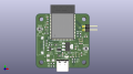
I am on my wits end trying to debug my usb-c socket/usb-otg port o nthe esp32-s3 and why it is not appearing on my laptop as a COM port for programming. I made a custom board for the first time using the esp32-s3. Since the esp32 s3 has built in D+ and D- lines for flashing firmware and debugging, I hooked up the USB-C connector directly to these pins via an ESD diode. On assembling the board, I cannot get myself to program the board via the USB-C cable. I have verified the the cable is perfect and is a data cable. I have probed the continuity from the USB-C receptacle to the esp32 and it is fine. I also probed the voltages on the lines to confirm the D+ line is being pulled high. I am however able to program the board via an external serial programmer via UART and can confirm that the board is able to go into download mode. I made a rookie mistake of not routing both D+ and D- lines together and hence can use it in only one orientation. I am attaching the layout and schematics below. Any help on what could be wrong is appreciated.
The only reason I can think of is that I messed up the routing of the USB lines.
Attachments
-
237.5 KB Views: 3
-
 99.8 KB Views: 2


