Problem with small mosfet

Thread Starter

zgaunc

Joined Aug 22, 2021
15
Hello All,
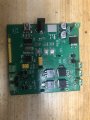
I designed a H bridge motor driver using two identical schematics. The reason is that I tried to test MOSFETs in different size. One circuit I used TO-252 MOSFETs, it worked perfectly well. In another circuit, I used small size sot23-3 AO3400 and AO3401 MOSFETs. It cost me more than 12 P and N channel MOSFETs, still not working for a single time. They were all short circuited. By wiring to the bigger one, it worked again. I don’t know why the sot23-3 MOSFETs are so easily damaged possibly during soldering or what. Anyone has clue about this problem? Thank you all.
 

Attachments

dl324

Joined Mar 30, 2015
16,839
F3710S has a significantly higher current rating than AO3400. What is the motor current? Do you have snubber diodes in the circuit? The IR parts are avalanche rated; the AO parts aren't.

A schematic would be helpful than a picture of a board.
 

Ian0

Joined Aug 7, 2020
9,667
How are you driving the upper MOSFET? How are you producing a gate drive voltage that is greater than the positive supply?
 

Thread Starter

zgaunc

Joined Aug 22, 2021
15
The motor curre
F3710S has a significantly higher current rating than AO3400. What is the motor current? Do you have snubber diodes in the circuit? The IR parts are avalanche rated; the AO parts aren't.

A schematic would be helpful than a picture of a board.
The motor current is very low. It’s just a 5v small motor. About 0.05A. The problem is that every time when I just solder these AO mosfet on the board and connect with power supply, some of the MOSFETs just got short circuit and start burning. Later, I use bigger to-252 MOSFETs and use thin wires to connect them on the corresponding pads of sot23-3. It worked fine. It means the circuit design is correct. I have the diode to protect the circuit. I began to suspect that I got bunch of faulty chips, but it’s not reasonable that more that 12 MOSFETs were faulty. Really drive mad.
 

Thread Starter

zgaunc

Joined Aug 22, 2021
15
The motor curre

The motor current is very low. It’s just a 5v small motor. About 0.05A. The problem is that every time when I just solder these AO mosfet on the board and connect with power supply, some of the MOSFETs just got short circuit and start burning. Later, I use bigger to-252 MOSFETs and use thin wires to connect them on the corresponding pads of sot23-3. It worked fine. It means the circuit design is correct. I have the diode to protect the circuit. I began to suspect that I got bunch of faulty chips, but it’s not reasonable that more that 12 MOSFETs were faulty. Really drive mad.
F3710S has a significantly higher current rating than AO3400. What is the motor current? Do you have snubber diodes in the circuit? The IR parts are avalanche rated; the AO parts aren't.

A schematic would be helpful than a picture of a board.
I don’t have schematic at the moment. The board picture I uploaded shows at the right lower area where to-252 IR mosfet H bridge driver circuit located. Left lower area is for sot23-3 AO MOSFETs H driver circuit. They are identical in schematic. I just copy the sot23-3 one from the to-252 design which worked very well.
 

Thread Starter

zgaunc

Joined Aug 22, 2021
15
F3710S has a significantly higher current rating than AO3400. What is the motor current? Do you have snubber diodes in the circuit? The IR parts are avalanche rated; the AO parts aren't.

A schematic would be helpful than a picture of a board.
I just uploaded a picture shows when I test bigger MOSFETs circuit. It worked fine
 

Attachments

Thread Starter

zgaunc

Joined Aug 22, 2021
15
How are you driving the upper MOSFET? How are you producing a gate drive voltage that is greater than the positive supply?
I use p channel MOSFETs as upper driver and I use two transistors to drive MOSFETs. Sending High signal to one transistor, then transistor start to conduct and pulls down the gate of the upper p channel mosfet. Sending low signal to another transistor. Like the picture I just uploaded. I do added diodes to protect MOSFETs.
 

Attachments

BobTPH

Joined Jun 5, 2013
8,804
That circuit is not good. When the input is low, both gates are at 6V. This might turn on both MOSFETs, creating a short circuit, depending on what voltage is needed to turn them on.

Bob
 

bertus

Joined Apr 5, 2008
22,270
Hello,

As @BobTPH said, the resistors on the gates can not have the same values.
Try these values as I printed in the schematic:
H-bridge-resistors.png
In this case, when the transistor inputs are low, the collector is pulled up harder.

Bertus
 

Juhahoo

Joined Jun 3, 2019
302
I use p channel MOSFETs as upper driver and I use two transistors to drive MOSFETs. Sending High signal to one transistor, then transistor start to conduct and pulls down the gate of the upper p channel mosfet. Sending low signal to another transistor. Like the picture I just uploaded. I do added diodes to protect MOSFETs.
Never ever connect MOSFET gates together on H-bridge !!! Else you have shoot through disaster ! Your bigger MOSFETs took the hit and survived, small ones died. Read the datasheet and understand how MOSFETS work, N and P channel MOSFETS conduct both at the same time at a certain point and all current shoots through both mosfets killing them.
Try reading this article first:
https://www.modularcircuits.com/blog/articles/h-bridge-secrets/h-bridge-control/

There are several methods of preventing that to happen, easiest is to use a dedicated H-bridge driver with built in mechanism, or you can set one up from discrete components which is explained in that link.
 
Last edited:

dl324

Joined Mar 30, 2015
16,839
The motor current is very low. It’s just a 5v small motor. About 0.05A. The problem is that every time when I just solder these AO mosfet on the board and connect with power supply, some of the MOSFETs just got short circuit and start burning.
The "big" MOSFETs you're using may be avalanche rated. The part number that I could read was. The small AO MOSFETs aren't. Once you fix the gate drive issue, add back EMF diodes.
 
Top