Physically, this circuit does not work ??
Or just in the simulation ??
If the simulation does NOT work is because you have several things to improve.
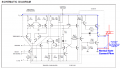
One of these is that no current flows through the Gate of the Triac.
You missed the red line appearing in the file that you attached. Triac that you placed in your scheme is generic and does not work. I changed Triac By L4004L5.
In the lamp parameters you assigned a value of 320, but You missed the V.
should be: 320V.
You'll notice that the lamp flashes, this is due to the speed of the computer (PC).
Note also that the gate of the Triac requires a resistor whose value is calculated knowing the electrical characteristics of the Triac which will be using.
It is convenient to set the parameters of the devices according to what is being done.
For example, the voltage applied to the lamp is 220V, but you programmed a voltage of 320V.
In the simulation, give it some time to turn on the lamp
One last note:
To develop your design in reality you must be very careful because you might get an electric shock.
This is because the line that is marked in red.
To avoid this you should use an Optocoupler to trigger the Triac.
Anyway, do several tests with the circuit I'll attached.
Physically, this circuit does not work ??
Or just in the simulation ??
If the simulation does NOT work is because you have several things to improve.
One of these is that no current flows through the Gate of the Triac.
You missed the red line appearing in the file that you attached. Triac that you placed in your scheme is generic and does not work. I changed Triac By L4004L5.
In the lamp parameters you assigned a value of 320, but You missed the V.
should be: 320V.
You'll notice that the lamp flashes, this is due to the speed of the computer (PC).
Note also that the gate of the Triac requires a resistor whose value is calculated knowing the electrical characteristics of the Triac which will be using.
It is convenient to set the parameters of the devices according to what is being done.
For example, the voltage applied to the lamp is 220V, but you programmed a voltage of 320V.
In the simulation, give it some time to turn on the lamp
One last note:
To develop your design in reality you must be very careful because you might get an electric shock.
This is because the line that is marked in red.
To avoid this you should use an Optocoupler to trigger the Triac.
Anyway, do several tests with the circuit I'll attached.
dear MrCarlos thank you for trying to help me , i simulate the circuit but the lamp neither work nor flash what is the wrong and if i use Optocoupler can you show me how to put it in the circuit
You Asked: If I use Optocoupler can You show Me how to put it in the circuit.
First of all We have to analyze why the circuit does not work in your simulator.
Your simulator Proteus ISIS (Version 8) is the DEMO version ??.
If You have DEMO version, that could be the reason that your circuit does not work.
The speed of Your PC might be another reason that your circuit does not work.
But hey: What about the simulation ??
When running the simulation, what you see on the screen ??.
When you press the button, can You see the little red boxes, for example, PIN3 In 555 ??
Telling me: The Lamp neither work nor flash. does not say anything about how to help.
Give me some inputs. More than four.
when i press push button the pin3 becomes high and the gate of triac but the lamp doesn't work. there is something i tried which i change the frequency of vsin from 50Hz to another less value and the lamp flashes
Hello spidermanIIII
By your answer I think is the speed of your PC.
I have a DELL LAP-TOP with Windows Vista operating system.
Your circuit works fine on it.
Unafraid Assemble your circuit with real components, for sure work.
Keep in mind that the TRIAC should be able to handle the current and voltage of the lamp that uses TO.
.
MrCarlos i have another question about (red line). Is the AC current affect the on the GND of 555 or affect capacitor C3 or C4 can you explain me please
Does not affect any of those things you mention.
The only one affected is the Gate of the Triac.
If you disconnect the red wire, the Triac will not work
! Warning! When your circuit is energized you could RECEIVE electric shock if you touch it. .
Hello spidermanIIII
It is relatively easy to do what you intend.
The optocoupler’s LED will be lit by 555 through its current limiting resistor.
Optocoupler outputs, which may be a photo Transistor or photo Diac, are connected, also through its resistance, to gate of the TRIAC, the other terminal is connected to the TRIAC-lamp which is currently joint.
Forward Current: Talking about electronic current,
It is one of the parameters of the diodes. Normally is specified in three settings: Minimum, Typical and Maximum. (Min. Typ. Max)
Is the current flowing in a semiconductor when it is polarized in the way (direction) of conduction.
It is the current that supports the diode without damage.
Reverse Voltage: The voltage in the opposite direction, which can polarize the diode without damaging.
 Facebook
 Google
 GitHub
 Linkedin