problem with output of linear ccd sensor

Thread Starter

mitra.gh

Joined Jan 1, 2021
7
HI
I am Mitra, a student of electronics.
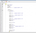
I am working on a project to build an optical spectrometer using a CCD linear image sensor. I am using TCD2253D sensor due to frequency limitation (I want to use the atmega32a microcontroller without using timers for driving pulses and in the simplest possible way). I have written an on-line program to generate drive pulses and the sensor becomes drive.
The problem is that the CCD output changes for all of the pixels at once! There doesn't seem to be any shifting going on. Covering part of the sensor causes all of the output pixels to change instead of only the ones being covered. in the other words for each SH pulse, the sensor output is zero. And if I turn the sensor on and off again, I have output again until SH becomes one and zero again. I have attached the output shape drawn in MATLAB, the driving pulses and the part of my program witch make pulses.
Am I overlooking something here?
 

Attachments

Deleted member 115935

Joined Dec 31, 1969
0
@mitra.gh Please remember we all help as best we can as volunteers.

I can not find a data sheet for the CCD you are using , could you post a link please.
I'm guessing its an old Toshiba part, in which case its !quality" must be of concern. These things are incredibly static sensitive, and are not very resistant to abuse. Is it a new part from an authorised distributor ?

Can you elaborate on the meaning of all outputs at once ?

is this not a serial output ? you get one analog level per pixel per clock ?

What do your clock and control waveforms look like into the CCD ?
 

Thread Starter

mitra.gh

Joined Jan 1, 2021
7
@mitra.gh Please remember we all help as best we can as volunteers.

I can not find a data sheet for the CCD you are using , could you post a link please.
I'm guessing its an old Toshiba part, in which case its !quality" must be of concern. These things are incredibly static sensitive, and are not very resistant to abuse. Is it a new part from an authorised distributor ?

Can you elaborate on the meaning of all outputs at once ?

is this not a serial output ? you get one analog level per pixel per clock ?

What do your clock and control waveforms look like into the CCD ?
Thank you very much for your attention and help
Yes, I think it is for 1998, but I chose this sensor because there was no frequency limit and I could work at low frequencies.
And because of my country, finding a newer sensor is very difficult and costly.
This device has one SH pulse for every 2776 phi pulses and ...
In fact, my problem is that it only works on the first pulse of SH, and after the second pulse sh, the output is zero.
@mitra.gh Please remember we all help as best we can as volunteers.

I can not find a data sheet for the CCD you are using , could you post a link please.
I'm guessing its an old Toshiba part, in which case its !quality" must be of concern. These things are incredibly static sensitive, and are not very resistant to abuse. Is it a new part from an authorised distributor ?

Can you elaborate on the meaning of all outputs at once ?

is this not a serial output ? you get one analog level per pixel per clock ?

What do your clock and control waveforms look like into the CCD ?
Thank you very much for your attention and your help, and I am so sorry! :)
Yes, I think it is for 1998, but I chose this sensor because there was no frequency limit and I could work at low frequencies.

And because of my country, finding a newer sensor is very difficult and costly.
This device has one SH pulse for every 2776 phi pulses and ...
In fact, my problem is that it only works on the first pulse of SH, and after the second pulse SH, the output is zero.

this picture is for second SH pulseWhatsApp Image 2021-01-05 at 09.18.52.jpeg

and this image is also output in the dark.
Of course, I used 4 pulses myself, which was later corrected.20201226_160414.jpg:)
 

Attachments

Thread Starter

mitra.gh

Joined Jan 1, 2021
7
@mitra.gh Please remember we all help as best we can as volunteers.

I can not find a data sheet for the CCD you are using , could you post a link please.
I'm guessing its an old Toshiba part, in which case its !quality" must be of concern. These things are incredibly static sensitive, and are not very resistant to abuse. Is it a new part from an authorised distributor ?

Can you elaborate on the meaning of all outputs at once ?

is this not a serial output ? you get one analog level per pixel per clock ?

What do your clock and control waveforms look like into the CCD ?
WhatsApp Image 2021-01-05 at 09.18.52.jpeg
the yellow one is out put of sensor and the blue one is PHI pulse.


kh1.jpgand yes this figure shows the output of the sensor when it is digitally received by the pc.
And any cross sign shows the SH pulse (I disconnected the sensor from the 12-volt power supply and reconnected it to have a re-output)
After the green cross, the sensor has output until the second SH pulse (the first red cross) sensor has zero output.

I hope I have explained clearly.
 

Deleted member 115935

Joined Dec 31, 1969
0
you need to compare the different control signals to that required in the data sheet
these older chips are sensitive to the clock phases / timing

just go through the diagram on page 7 of the data sheet, and check each timing,

How are you controlling the light ? particularly the inferred, this sensor has no IR filter on it,
How are you controlling the sensitivity / exposure ?
 

Deleted member 115935

Joined Dec 31, 1969
0
If my signals were wrong you ask.
yes the sensor could give out anything, including being broken.

If you light was to high, you saturate, if your integration is wrong you saturate or get nothing out.
If you get the timings to wrong for too long, then all best are off as to the state of the CCD.

You have also not replied as to is this a new CCD, or is it an old one that may / may not work.

Sorry,
with the limited info you have passed on , there is not more that o can say than check with a scope that all your signals to the CCD meet all the trimming and voltage levels in the data sheet.

If they do, then then the CCD should work, if it still does not, the CCD is broken.

You just have to turn the handle and find the problem,

One thing I do not in the article you sent, is that the timings are done by internal timers of the processor, and in exact ratios, such that the edges of the control pulses are defined and controlled phase to each other. I can only see the arduino delay function in your code, which is very different.
I know you say in the original post you don't want to use the timers, but timers were used for a reason in the article.
 
Top