Problem with latching ne555 circuit

Thread Starter

victorduchateau

Joined Jun 26, 2019
8
Hi everyone


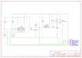
I'm designing a circuit for a fog light switch in Europe. Here the fog light switch has to be a mono stable push button so I'm using a simple ne555 latching circuit as shown in the attachment.

12V power is connected to the headlights.

I've tested this circuit on many cars now and it works just fine. However I now have to use this circuit on a Chevy Suburban.
The problem I'm having is that sometimes when I turn the headlights on, the fog light will turn on as well. The circuit in it's hole doesn't function properly either. Sometimes the circuit latches but other times it doesn't.

Obviously there is a solution for this problem but I'm kind of clueless atm.
Could it maybe be resolved by using a bigger capacitor?

Thanks
 

Attachments

AlbertHall

Joined Jun 4, 2014
12,346
First an observation - I don't expect this is anything to do with your problem.
R4, R5, R6, Q1, and U2 are unnecessary. Simply connect the left hand end of R7 to U1 pin 3.

Now onto your problem. Automotive electrical systems are very noisy and you have no decoupling capactors, Connect say 100uF and 100nF capacitors across the supply to the NE555 very close to the '555 pins.
 

Thread Starter

victorduchateau

Joined Jun 26, 2019
8
First an observation - I don't expect this is anything to do with your problem.
R4, R5, R6, Q1, and U2 are unnecessary. Simply connect the left hand end of R7 to U1 pin 3.

Now onto your problem. Automotive electrical systems are very noisy and you have no decoupling capactors, Connect say 100uF and 100nF capacitors across the supply to the NE555 very close to the '555 pins.
Thanks for the reply!

Thanks for optimizing my circuit. Q1 is overkill but the optocoupler is necessary because I actually don't connect the ground of the fog light directly to this circuit.

What goes for the capacitors, to which pins do you suggest I connect the capacitors and how?

Thanks
 

Thread Starter

victorduchateau

Joined Jun 26, 2019
8
I don't see that the grounding of the foglight is relevant, providing the latching circuit is connected to vehicle ground at pin 5 of CN1.
I know what you mean. However I tested the circuit without the optocoupler and it doesn't work. Very odd but the optocoupler fixes the problem
 

AnalogKid

Joined Aug 1, 2013
11,036
What goes for the capacitors, to which pins do you suggest I connect the capacitors and how?
The 555 power supply pins are 1 and 8. Connect a 100 nF ceramic cap between them, as close as possible with the shortest possible leads. Also connect a 10 uF - 100 uF electrolytic cap in parallel with the 100 nF ceramic. Be sure to observe the electrolytic cap polarity.

ak
 

crutschow

Joined Mar 14, 2008
34,409
Also connect a 10nF cap from the CONT pin 5 to ground.

I'm not sure I understand the operation of the circuit.
What's the purpose of R1 and C1?
 

bertus

Joined Apr 5, 2008
22,276
Hello,

I have blended in a translation of the text of the connector:

Schematic_Fog-Light_Translation.png
Perhaps this will make things more clear.

@victorduchateau , Can you explain the function of the two switch wires?

Bertus
 

crutschow

Joined Mar 14, 2008
34,409
Debounce for a momentary switch, to allow the 555 to toggle cleanly.
I see no reason for that, as the 555 will trigger on the first bounce, and subsequent bounces will have no further effect on its state.
So the switch just needs to be connected to ground and R1 C1 eliminated.
 

crutschow

Joined Mar 14, 2008
34,409
LTspice says R1/C1 are needed to get the toggle action.
Okay.
I didn't understand that a toggle action was needed, but I see now how that works.
I thought the light would be turned off with the power.
So R1C1 charges to the opposite polarity to allow the toggle action on the next button push.

victorduchateau, you may have to add an RC power-on reset function to the RESET pin 4 if you still have a problem with it powering up into the ON state.
 
Last edited:
Top