Problem with diodes/zeners

Thread Starter

PsySc0rpi0n

Joined Mar 4, 2014
1,755
Hi...

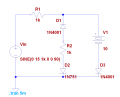
I'm trying to solve a problem with zeners and diodes.

The circuit is attached but for some reason that I can't figure out, LTSpice is taking for ever to simulate the circuit.
I've also attached a small image that shows what LTSpice is doing.

First of all, can you help me figuring out why LTSpice is taking for ever to simulate the circuit?
 

Attachments

Thread Starter

PsySc0rpi0n

Joined Mar 4, 2014
1,755
Ok, I was discussing this problem with some "netfriends" and we came to some conclusion that LTSpice might be trying to calculate some value that is impossible to solve or something like that.

I am using standard.dio file from LTSpice wiki site and there are there some models of this family 1N75x.
I have tried with 1N750 and 1N751 and both gave that problem.

The models inside the file are:

Code:
.model 1N750 D(Is=.88f Rs=.25 Cjo=175p M=.55 nbv=1.7 bv=4.7 Vj=.75 Isr=1.86n Nr=2 Ibv=20.245m Ibvl=1.96m Nbvl=15 Tbv1=-21.3u Vpk=4.7 mfg=OnSemi type=Zener)
.model 1N751 D(Is=1.004f Rs=.5875 Ikf=0 N=1 Xti=3 Eg=1.11 Cjo=160p M=.5484 Vj=.75 Fc=.5 Isr=1.8n Nr=2 Bv=5.1 Ibv=27.721m Nbv=1.1779 Ibvl=1.1646m Nbvl=21.894 Tbv1=176.47u Vpk=5.1 mfg=Motorola type=zener)
.model 1N752 D(Is=1.154f Rs=.9471 Ikf=0 N=1 Xti=3 Eg=1.11 Cjo=150p M=.5788 Vj=.75 Fc=.5 Isr=1.625n Nr=2 Bv=5.6 Ibv=62.583m Nbv=.62382 Ibvl=631.96u Nbvl=50 Tbv1=267.86u Vpk=5.6 mfg=Motorola type=zener)
.model 1N754 D(Is=1.616f Rs=1.818 Ikf=0 N=1 Xti=3 Eg=1.11 Cjo=120p M=.5117 Vj=.75 Fc=.5 Isr=1.698n Nr=2 Bv=6.8 Ibv=2.8814 Nbv=.28248 Ibvl=1.9426e-6 Nbvl=.27168 Tbv1=485.29u Vpk=6.8 mfg=Motorola type=zener)
.model 1N755 D(Is=2.077f Rs=2.467 Ikf=0 N=1 Xti=3 Eg=1.11 Cjo=104p M=.5061 Vj=.75 Fc=.5 Isr=1.645n Nr=2 Bv=7.5 Ibv=2.5701 Nbv=.39227 Ibvl=4.0222e-5 Nbvl=.25042 Tbv1=533.33u Vpk=7.5 mfg=Motorola type=zener)
.model 1N757 D(Is=2.453f Rs=2.9 Ikf=0 N=1 Xti=3 Eg=1.11 Cjo=78p M=.4399 Vj=.75 Fc=.5 Isr=1.762n Nr=2 Bv=9.1 Ibv=.48516 Nbv=.7022 Ibvl=1m Nbvl=.13785 Tbv1=604.396u Vpk=9.1 mfg=Motorola type=zener)
Then I tried to used the same 1N750 model but by means of ".model...." directive but the problem was still there.
Then I tried to change the position of the zener in the circuit using LTSpice standard library (by right clicking the diode and picking the 1N750 from the list) and the problem was gone.
Then I tried another zener from another family at the original position in the circuit and the problem was also gone.

I have made there tests but I got no exact conclusion. Could it be some bug in those zener models that came up due to the position of the zener at the circuit?

Anyway, I'm using another model!

I'm trying to sort something out in paper. I'll come back here when I have something!
 

Thread Starter

PsySc0rpi0n

Joined Mar 4, 2014
1,755
I started by drawing a table with all possibilities.
Then I have redraw the original circuit and replaced the diodes and the zener by their equivalent models regardless if they are possible or not and regardless the conditions that makes them work for each possibility.

But now I'm struggling to find each condition values in terms of voltages and also to determine which possibilities are in fact possible and which are not!

I was trying to see what would happen if Vin was -15V.
If I have Vin = -15V, D2 would be working as a Zener (I think) because voltage at it's cathode would be more negative than voltage at it's anode (we have a 10V battery forcing a positive voltage at Vout node which is at D1 cathode/V1 positive side), D1 would be OFF because we would have a more negative voltage at it's anode than at it's cathode and D2 would be ON because we have a more negative voltage at it's cathode.

In this case, and if my assumptions are correct, I would have -15V at D2 cathode and -20V at zener's anode. But as D1 is OFF this branch wouldn't matter for my Vout equation. Is this correct?
 

Attachments

ericgibbs

Joined Jan 29, 2010
18,766
Then I have redraw the original circuit and replaced the diodes and the zener by their equivalent models regardless if they are possible or not and regardless the conditions that makes them work for each possibility.
Please post the asc file which shows the equivalent models.
 

Thread Starter

PsySc0rpi0n

Joined Mar 4, 2014
1,755
Please post the asc file which shows the equivalent models.
I've done that on paper. That's the images I've uploaded. I have replaced diodes by voltage sources when they're ON, and by an open-circuit when their OFF and by an inverted voltage source for the zener.
Then I tried to find the Vout value/expression!
 

ericgibbs

Joined Jan 29, 2010
18,766
If I have Vin = -15V, D2 would be working as a Zener (I think) because voltage at it's cathode would be more negative than voltage at it's anode (we have a 10V battery forcing a positive voltage at Vout node which is at D1 cathode/V1 positive side),

D1 would be OFF
because we would have a more negative voltage at it's anode than at it's cathode and D2 would be ON because we have a more negative voltage at it's cathode.
As D1 and Z2 are in the same path,how can one be On [conducting] and the other be Off [non conducting]

In this case, and if my assumptions are correct, I would have -15V at D2 cathode and -20V at zener's anode. But as D1 is OFF this branch wouldn't matter for my Vout equation. Is this correct?
What do think is happening in the D3 , V1 path.?? when you have a -15V at Vin.?
 

Thread Starter

PsySc0rpi0n

Joined Mar 4, 2014
1,755
Well, I have posted that post unintentionally because I saw that I was wrong before I post it. Probably forgot to correct the text.

Anyway, with Vin = -15V, I would have 15V at Zener's cathode and at D1 cathode we have 10.7V (10 + 0.7 from V1 + D3).
The tricky part for me is to analyse what is happening at Zener's and D1 anodes. Because if zener is working as zener, the voltage at it's anode would have to be Vzener more negative than at it's cathode, therefore, -20V, and if D1 was also ON, the voltage at it's anode would have to be 10V (from V1) + 0.7V (from Vd1).

So at the resistor R2 I'm not sure how to analyse what's going on with voltage as we have a negative voltage from the zener and a positive voltage from D1.
 

ericgibbs

Joined Jan 29, 2010
18,766
Hi,
Anyway, with Vin = -15V, I would have 15V at Zener's cathode
Do you really mean 15V at the zeners cathode.? That would mean you would have a negative voltage on the zeners anode. ie: > 15 V across the zener.!

Consider that the zeners cathode is 0V and the anode is at some negative potential, via the diode etc.

You are confusing yourself.:)

EDIT:

Added image showing part of your circuit, does this make it easier to follow.?
 

Attachments

Last edited:

Thread Starter

PsySc0rpi0n

Joined Mar 4, 2014
1,755
Sorry, I mean -15V at zener cathode. And if a zener when is working as a zener must have a voltage at it's anode more negative by Vzener volts than at it's cathode, then I would have -20V (-15V - 5V = -20V) at it's anode, assuming Vzener = (-)5V.

If I consider 0V at Zener's cathode and it is working as a zener, then at it's anode I would have -5V, right?
But then I don't understand what you mean by "...and the anode is at some negative potential, via diode D1".
 

Thread Starter

PsySc0rpi0n

Joined Mar 4, 2014
1,755
Look at my EDIT post #10
Let me know if you can follow it OK.
Yes, I can understand it perfectly if I don't look to Vin... How is it supposed to have 0V when the '+' sign of the Vin is directed to the Zener's cathode? Apart of this I can understand it!
 

ericgibbs

Joined Jan 29, 2010
18,766
OK.
Ref V1 and D3.
Disconnect that path from the rest of the circuit, so you only have V1 and D3 connected in series. See image.

Now connect a 1k across the ends so you have a 'loop', how much current do you think will flow in the 1K.?
 

Attachments

Thread Starter

PsySc0rpi0n

Joined Mar 4, 2014
1,755
That is kinda tricky but I think we will have an open circuit there because we have 0V at the diode anode and a more positive voltage at it's cathode so probably no current will flow across that resistor!
 

Thread Starter

PsySc0rpi0n

Joined Mar 4, 2014
1,755
Ok, I think now D3 will be conducting but as there is no resistance in that circuit, I can't say if there will be current flowing. Unless we consider internal resistance from batteries and the diode itself!
 

ericgibbs

Joined Jan 29, 2010
18,766
Not really.
Consider that the batteries are in series.! so you now have 25V reverse volts across the diode , instead of the original 10v!

So D3 is still reversed biassed and not conducting.

Do you follow that

EDIT:
Redrawn to show the series batteries.
 

Attachments

Top