Facebook
 Google
 GitHub
 Linkedin
I breadboarded an Astable Multivibrator Driving Circuit which makes two LED blink at the rate I want but when I use an LED stick it looks dim, not fully bright.
I started with this theory:
https://www.electronics-tutorials.ws/waveforms/astable.html
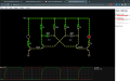
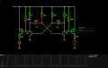
Then put together this circuit (Falstad):
https://tinyurl.com/yh48yt8n (LED blink at around 1Hz, transistor are 2N3904 and I have tried some BC547 and 2N2222 with the sam result)
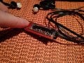
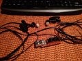
I would like to replace the red LEDs with an LED stick. These work at 5V and seem to pull close to 350mA.
When I replace the red LED+resistor with the LED stick, it blinks at the correct rate but it doesnt appear to be fully ON.
Here is a video:
(in this video they are blinking faster because I was testing different resistors)
(I have some AO3400 N-Mosfets and AO3401 P-Mosfets here I that's the way)
Thank you in advance.
I started with this theory:
https://www.electronics-tutorials.ws/waveforms/astable.html
Then put together this circuit (Falstad):
https://tinyurl.com/yh48yt8n (LED blink at around 1Hz, transistor are 2N3904 and I have tried some BC547 and 2N2222 with the sam result)
I would like to replace the red LEDs with an LED stick. These work at 5V and seem to pull close to 350mA.
When I replace the red LED+resistor with the LED stick, it blinks at the correct rate but it doesnt appear to be fully ON.
Here is a video:
(I have some AO3400 N-Mosfets and AO3401 P-Mosfets here I that's the way)
Thank you in advance.
Attachments
-
 48.6 KB Views: 16
 -
 136.9 KB Views: 16