Pressure sensor signal amplification

Thread Starter

jts1705

Joined Apr 4, 2019
5
Hello everybody,

I am a student who is developing a pressure sensor device for a medical application. I need to measure pressures between 0 and 50mmHg. Therefore, I am using arterial pressure sensors that suit my purposes (http://www.icumed.com/products/critical-care/blood-pressure-monitoring/transpac-it.aspx).
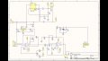
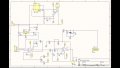
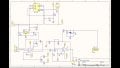
I need to amplify, filter and condition the signal before Arduino UNO can read it.

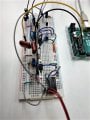
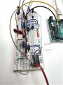
I've designed an schematic that I think can work, but now I am trying everything in a protoboard and it does not work. I have tested with a voltmeter partial voltages and the DCDC converter seems to be not working good. It does not give any output signal. I have checked again its datasheet and seems like it has a CTRL pin... but I do not really think it is the reason why it does not work. (https://eu.mouser.com/datasheet/2/468/RS-S_D_Z-958418.pdf). I do not know if the DCDC converter is broken or if I have performed a mistake before...

I would be very very very thankful if any of you could give me his/her opinion.
I attach the schematic and two photos of the protoboard.

Thank you very much!!
 

Attachments

ericgibbs

Joined Jan 29, 2010
18,767
hi jts,
Welcome to AAC.
Your circuit shows AR2 as a TL062, but its a IN128 symbol.?
Also R5 for Vref on AR1 should be a low impedance source to ensure the CMRR spec is met.
E

EDIT:
Confirm the power rails to AR2, your wire colour coding is confusing.
 

Attachments

Last edited:

danadak

Joined Mar 10, 2018
4,057
You meeting the minimum load requirements on the DC/DC, its wants
10% of its rating as min load. The INA and 072 will not meet that. Spec
sheet not specific on this but I am thinking it wants 10% on each of its
outputs.

You might want bypass caps right at OpAmp and I/A, tantalum, to min
noise. Also add .1 uF ceramic right at DC/DC outputs.

And on proto build a good ground busbar, relying on solderless B-B to form
a good ground is like betting on the lottery. You are working with very low
level signals. Plus you have a DC/DC switching converter that wants to make
100's of mV of noise and spikes into ground loop.

As an aside different cap technologies, for the same value, have very large
ESR differences.


Regards, Dana.
 
Last edited:

Hymie

Joined Mar 30, 2018
1,277
You need to sort out the DC/DC converter to have any chance of the circuit working.

Having bread-boarded many circuits in the past – this one is quite complicated for a beginner; you only need one failed connection or incorrectly connected component, with the result that there is a high probability of the circuit not working as intended.

My advice is to bread-board the DC/DC converter in isolation to discover what is wrong.

It also appears that the first op-amp amplifying the pressure signal is configured with no feedback – resulting in a very high open loop gain.

If I were developing this circuit I would consider constructing it on vero-board with generously spaced components allowing reasonably easy modification.
 

AnalogKid

Joined Aug 1, 2013
10,990
The DC/DC datasheet you linked is not the correct sheet for the part on your schematic, so either the schematic is incorrect or the datasheet is the wrong one. For example, the schematic shows 24 pins, but the datasheet has 8. Either way, without the correct pinout it is difficult to say what is going on.

As above, you really should add decoupling capacitors to each opamp power pin. Analog Devices recommends a 0.1 uF ceramic and 10 uF electrolytic capacitor in parallel, located as close as possible to the IC power pins, with the shortest possible leads.

What is the input voltage running the board?

ak
 

sghioto

Joined Dec 31, 2017
5,383
The output from the DC-DC converter is on pins 6 and 7.
From the photo it looks like you are on 7 and 8.
Also not sure if the polarity is correct on the input.
SG
 
Last edited:

AnalogKid

Joined Aug 1, 2013
10,990
IF the part on the protoblard is the one in the linked datasheet
AND IF the intent of the schematic (bipolar power sources for the ICs) is correct
THEN the wiring is incorrect.

This is why it is important to have a schematic you can trust. The schematic shows both ICs connected to both +12 V and -12 V sources. Yet your photo shows only two wires to the power DC/DC output pins. It looks like you have the circuit running on -12 V (grey wire) and GND (blue wire) with no connection to the +12 V output.

I strongly suggest that you correct the schematic first, paying careful attention to the datasheet. Then make the wiring agree with the schematic. Then test things.

ak
 

Thread Starter

jts1705

Joined Apr 4, 2019
5
Thanks to all. I followed all your instructions and I considered to remake the schematic and correct its mistakes. (I do not have Altium license anymore so I did it as I could).
-->I have corrected the pins in the DCDC converter according to the datasheet and also the pins in TL062 (although they were wrong in the schematic I think I was doing it right in the protoboard).

I do not really know why, but now the DCDC converter seems to be working but it gives almost +14V in Out+ and -10.10V in Out-. Instead of +12V and -12V that is what I was expecting. However, I think this should be enough to supply to the INA128 and TL062.

As I told you, I am starting in electronics and there are several things which I do not really know if I have understood from your suggestions. Forgive me about that. However, I think that I have included decoupling capacitors to each opamp power pin. I put them above in the schematic. Maybe are too far from the ICs in the protoboard? Please, correct me if I am wrong.

AnalogKid, the input voltage is 12V.
Dana, to set the gain of the INA128 I am using a potentiometer. Isn't this ok? I did the calculations to set a minimum and a maximum gain and then I obtained the required resistors.
 

Attachments

ericgibbs

Joined Jan 29, 2010
18,767
hi jts,
The gain pot is fine.
Measure and post the voltage rails on the actual pins of the two IC's, post what you measure, we can then confirm the supply lines.
E
 

AnalogKid

Joined Aug 1, 2013
10,990
There still is no connection between the DCDC1's output ground (pin 7) and the circuit ground. Without this, the outputs can float away. The only ground reference is the input ground (V-), which is capacitively coupled to the outputs. The outputs could be +37 V and +61 V -- still 24 V apart, but not referenced to the system.

ak
 

Thread Starter

jts1705

Joined Apr 4, 2019
5
Hi all!

I have included the modifications you mentioned me. Thanks again.
Dana, I think I have done now what wou were suggesting me before, but, did I do it ok? (Still can not include them in the protoboard because I need to go and buy them, but I will). :)
AnalogKid, I also did the connection of pin 7 to the GND. Now I have 12V and -12V. :)
Eric, IC's are now being supplied with 12V and -12V as I expected.

However, I still don't get any signal in the Arduino signal. I think something is wrong with INA128. I have tested and the voltage reference AD581JH is supplying the pressure sensor with 10V as expected, so I think this part of the circuit is OK. But in the output of the INA128 I am getting -1.84V which is very very strange... Do you know what is happening? :( (I include another photography of this part of the protoboard).

Again, thank you very much,

Best wishes,
Joel

MOD: Tidied your images.E
 

Attachments

Last edited by a moderator:

ericgibbs

Joined Jan 29, 2010
18,767
hi jts,
Does adjusting the R5, 2K Vref pot change the output on pin#6 of the INA128.?

What gain have you set R3 to give on the INA128.?

What voltage do you measure across pins #2 and #3 of the INA128.?
E
 

Thread Starter

jts1705

Joined Apr 4, 2019
5
Hello everybody,

Sorry for the delay.
I manage to solve all the problems today. The outputs of the transducer where twisted and I obtained all the time negative values. :confused:

However, now it works perfect and that is thank you to all you!!
I really appreciate your help! :)

Best wishes to all you!!

Joel
 
Top