Pressure Sensor Signal Amplification

Thread Starter

Physnano

Joined Aug 18, 2015
17
The way I see it there are two issues so far:
1) I do not know the precise pinout of my sensor.
2) There may be something wrong with my amplification stage.

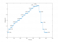
I rewired the Sensor, energizing 5V across pins 2 and 5. The response as I swing from 0 - 15 PSI and back down to 0 PSI is attached. I am measuring between pin 4 (+OUT) and pin 6 (-OUT). (Measuring across pin 3 and 6 does nothing!) These correspond to the MPS20N0040D-D data sheet, except for pin3 which on my sensor is actually pin 4. I see roughly 40 mV change for 15 PSI difference. My voltage baseline for 0 PSI is ~ 1.98V

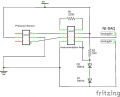
After hooking +OUT of the sensor (pin 4) to +IN of my OPA (pin 3) and -OUT of sensor (pin 6) to -IN of my OPA I am still getting no amplification. I am reading a base voltage of ~4.3 - 4.5 V

I have attached a new schematic. Should I just play around with my Rg now or is there something else I am doing fundamentally wrong in the amplification stage?

Thanks for everyone's help so far.
 

Attachments

ericgibbs

Joined Jan 29, 2010
18,766
hi Phy,
This is your circuit in LTS simulation.
The Sensor pin out is based on the PDF you posted, you may need to correct for any errors in the PDF pins.

Note you will need a 100R pot across pins 1 and 6 of the sensor in order to balance the bridge to Zero output
I have made notes in Blue.

Ask if you have a problem

E
EDIT: I would recommend that filter circuit.
 

Attachments

Thread Starter

Physnano

Joined Aug 18, 2015
17
So I think that I have it working reasonably well. See the attached graph. My question is regarding the noise at this point. At each pressure there is quite a bit of fluctuation. I have incorporated the required filter and capacitors to stabilize 5V supply. Additionally it seems that there is quite a bit of non-linearity (esp between 1 and 2 psi and 5 and 6 psi) is this normal? Am I expecting too much from this sensor? What further approaches could I take to minimize non-linearity and noise? The data sheet for the AD620 suggests an AD705 picoampere opamp for pressure sensor operation. Should I go ahead and try this?

I am Plateauing in the attached graph. Any further increase in PSI does not increase the measured voltage. This could explain (non-linearity between 5 and 6 psi I suppose)
 

Attachments

ericgibbs

Joined Jan 29, 2010
18,766
hi Phy,
You could try adding another 1N914 diode in series with the two existing diodes used for Vref, this should lift the the Vref to ~2.0V, this should improve the low level linearity.
With ref to the AD705 that will give a more stable 2Vref

The non linearity above 5 PSI could be due to the AD620 starting to limit at its +Vout limit. The d/s for the AD620 shows a Vout limit of ~3.5V with a 5V supply.?
For a full 0v thru 5v output I usually add a MCP6002 [dual rail to rail OPA], this OPA removes the +2V offset voltage and also amplifies the actual output to ~0v thru +5v.

What is the common mode voltage at the AD620 input pins.? [post this voltage]

With ref to the noise you could increase the 1k's at the AD620 inputs to say 10k.
Also how is the sensor connected to the AD620.??? , is the wiring short as possible, screened or at least a twisted pair.?

E
 

Thread Starter

Physnano

Joined Aug 18, 2015
17
Eric,

One more question, what exactly do you mean by a 100R pot across sensor pins 1 and 6? I have a variety of potentiometers at my disposal what does the "100R" mean? Variable resistor configuration?

Thanks
 

ericgibbs

Joined Jan 29, 2010
18,766
hi Phy,
On your sensor data sheet it shows pins #1 and pin 6 are at the junction of two of the bridge resistors.
To make the bridge complete it is necessary to join those two pins.

However as most bridges have a slight imbalance signal output with a Zero load [pressure], it is common practice to have a method of Zeroing the bridge.
If instead of joining pins 1 and 6 together, insert a low value multi turn potentiometer between pins 1 and 6 and take the negative output signal to the OPA from the wiper of the pot.

Using the pot you can trim the bridge to give Zero mV at zero loading.
A 100 Ohms pot should be OK as your bridge resistors are approx 5k.

I did draw the pot on the SIM image I posted. OK

E
 

Attachments

Thread Starter

Physnano

Joined Aug 18, 2015
17
Hello everyone,

Major success today. The circuit seems to be working flawlessly. See attached calibration curve. Outputs are linear over the stated range of the sensor. Linearity decays around 7.5 PSI+. I will test drift by running a long time trace tonight. I can provide schematic to anyone interested.

Thanks for the help everyone.
 

Attachments

Hello everyone,

Major success today. The circuit seems to be working flawlessly. See attached calibration curve. Outputs are linear over the stated range of the sensor. Linearity decays around 7.5 PSI+. I will test drift by running a long time trace tonight. I can provide schematic to anyone interested.

Thanks for the help everyone.

hi Phy,
I am working on similar project using ARDUINO UNO , are you using the same circuit as you have attached above.
Eagerly waiting for your reply

Thank You
 

DC_Kid

Joined Feb 25, 2008
1,072
is this project an exercise? the BMP 180 is everywhere on breakout boards for arduino for about $4 (or less). BMP 180 also gives you temp
 

amohammed

Joined May 2, 2016
1
hello i am very confused with the pin of MPS20N0040D-D can any one say me correct pin configuration and i have to measure blood pressure with this sensor ..so let me know the pin of this sensor
thanks
abdul
 
Top