 Facebook
 Google
 GitHub
 Linkedin
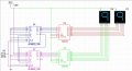
You made everything almost perfect, except for the fact that the counter does not load its preset inputs on power up, so read what signal can do this instead.Hi, so the reason I only had one counter and display was that I was making sure I had inputting numbers correct before I added in another counter, because I want it to start at the number 30 and count down to zero. This is my new schematic I have drawn, but no matter the inputs for presets, it starts them both at 9. As you can see, for the first digit, I have 0011 going in so it will output 3. And for the second digit, I have 0000 going in so the output will be 0, hence start at 30. Is something hooked up where its not supposed to be?
Also make sure your reset lines are connected to either ground (by default) or 5V (to reset the counter). In the schematic they just seem to be connected together.


")


