Precision full-wave rectifier - clamped rectified negative cycle

Thread Starter

Dritech

Joined Sep 21, 2011
907
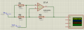
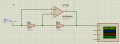
Hi @crutschow , I built the full-wave rectifier circuit you shared in past #4.
This worked without any problems, but I would like to understand how it actually works. Is there a specific name for this type of circuit configuration as I cannot find any similar circuit on the internet ?
 

MrAl

Joined Jun 17, 2014
13,709
Hi all,

I am experimenting with an enveloping circuit (precision full-wave rectifier) which I found here
When simulating this and increasing the input peak-to-peak to 4.5V (supply is 5V and the op amp has a rail-to-rail input output), I am getting a clamped rectifier negative cycle as evident from the snapshot below.
I tried various diodes, resistance values, op-amps, but this configuration is the best I can get.
Is there a way to prevent this from happening?

View attachment 187518
View attachment 187517
Many op amps can not put out a rail to rail signal.
 

Thread Starter

Dritech

Joined Sep 21, 2011
907
Many op amps can not put out a rail to rail signal.
Hi Mr AI. I managed to get the circuit to work using the circuit suggested by @crutschow in post #4 , but unfortunately I cannot find any reference to this particular circuit on the internet and I wish to understand how it actually operates.
 

crutschow

Joined Mar 14, 2008
38,529
I wish to understand how it actually operates.
This is the tricky part:
U1 acts as an inverter when node 2 (op amp + input) is grounded, and acts as a follower when node 2 is not grounded (sees the Input voltage through R2).
Once you understand that, then the rest is fairly simple.

When the input goes high, U2 sees the plus voltage at its (-) input so the output stays low.
This means D1 is reversed biased by the positive input, and thus node 2 is not grounded, causing U1 to act as a follower (non-inverting).

When the input goes low, U2 sees the negative voltage and its output goes high, just enough just to keep node 2 equal to the (+) input (ground).
Since node 2 is now maintained at ground potential, U1 acts as a gain-of-one inverter giving a positive output for the negative input.

Thus the Out of U1 is a positive going, full-wave rectified signal of the input waveform.

Make sense?

1587760794215.png
 

MrAl

Joined Jun 17, 2014
13,709
Hi Mr AI. I managed to get the circuit to work using the circuit suggested by @crutschow in post #4 , but unfortunately I cannot find any reference to this particular circuit on the internet and I wish to understand how it actually operates.
Hello,

It looks like the upper op amp has a gain of 2 for non inverted inputs and a gain of -1 for inverted inputs. Thus when the input is positive it has an overall gain of 1 and so the input goes to the output.
When the input goes negative the upper inverts to +1 again and the lower clamps the non inverting input to ground so that the upper can work as a regular inverting op amp circuit with a gain of -1.
The overall circuit thus acts as a full wave rectifier.
Some caution might be that the output may or may not go entirely to ground during the valley portions but that may or may not make a difference to the application. The output may or may not go to the positive rail either.
 

MrAl

Joined Jun 17, 2014
13,709
I don't understand that statement.
That would be true if R3 were grounded but it is not.
Yes it is grounded when we use what is called superposition.
We can treat the input as two different sources and thus be able to use superposition to obtain the output of the upper op amp. When the signal goes negative we have that plus the effect of the lower op amp.
Try that.
 

MrAl

Joined Jun 17, 2014
13,709
Sorry, I know what superposition is, which works well for multiple sources in a circuit, but it seems like convoluted thinking to use for this circuit with only one source.
Nah, it actually helps because it helps to isolate the two or more input routes into circuits that are more familiar. If you look at a non inverting op amp amplifier you see a gain of G+1, and if you look at an inverting amplifier you see a gain of -G. Superposition quickly yields an overall gain of:
OG=G+1-G=1
It took me just a few seconds to figure out the operation of the top amp that way didnt have to do any real lengthy math or simulation. I think it would be hard to match that simplicity with any other type of analysis but you are welcome to try.

This helped in other circuits too i had to analyze in the past. It usually help more when the two circuits associated with one input are complicated on their own and you dont want to use a full Nodal or something because they are not extremely complicated. This actually came up in this forum previously also.
 

Thread Starter

Dritech

Joined Sep 21, 2011
907
Hi again,

I am understanding how the circuit is operating when the input is negative, but apparently my brain is not making sense of this circuit when the input voltage is positive :(

Lets say that the supply of the op-amps in single rail 5V and with virtual ground Vs/2 (i.e. 2.5V)

So, when the input voltage is negative, the circuit will be equivalent to the one below, correct?

1587837258402.png

Also, when Vin is above 2.5V (positive), the circuit will be equivalent to the one below. How is this actually operating as a voltage follower?

1587837386955.png
 

Attachments

crutschow

Joined Mar 14, 2008
38,529
I think it would be hard to match that simplicity with any other type of analysis but you are welcome to try.
Okay, I'll try.
How about below?
Also, when Vin is above 2.5V (positive), the circuit will be equivalent to the one below. How is this actually operating as a voltage follower?
Due to its high open-loop gain, an op amp always tries to maintain the differential voltage across its two inputs very near zero.
If you look at your bottom circuit, you can see that the only way for that to occur is if there is no current through R2 and R3, which is only when the output voltage equals the input voltage, hence is is operating as a follower.

No math or superposition required.
 
Last edited:

Thread Starter

Dritech

Joined Sep 21, 2011
907
Thank you for the explanation. I can now fully understand the operation of the circuit when it operates as a voltage follower, but I am still missing the basics when the circuit operated as an inverting amplifier. In past #24 you mentioned that "When the input goes low (i.e. below 2.5V in this example), U2 sees the negative voltage (with reference to Vs/2, that is anything below 2.5V) and its output goes high, just enough just to keep node 2 equal to the (+) input (ground). Since node 2 is now maintained at ground potential, U1 acts as a gain-of-one inverter giving a positive output for the negative input."

At which point does the (-) input of U2 sees the negative voltage? I did the circuit below which represents this node, where the center note is the (+) of U1, 2.5V is the output from U2 when the voltage is below virtual ground and the slope is the changing input voltage. At no point the voltage at R4(2) goes below 2.5V, so how can the (-) of U2 ever sees the 'negative' voltage? what am I missing/misinterpreting please?

1587890704156.png
 

MrAl

Joined Jun 17, 2014
13,709
Okay, I'll try.
How about below?
Due to its high open-loop gain, an op amp always tries to maintain the differential voltage across its two inputs very near zero.
If you look at your bottom circuit, you can see that the only way for that to occur is if there is no current through R2 and R3, which is only when the output voltage equals the input voltage, hence is is operating as a follower.

No math or superposition required.
Well if you want to get that over simplistic then why didnt you just say:
"The circuit works".

However now that we've talked about it i think a full analysis is in order anyway. It would be good to consider the effect of the ability of the outputs to get to non zero when they should be exactly zero. I havent gotten to that yet though :)
 

MrAl

Joined Jun 17, 2014
13,709
Thank you for the explanation. I can now fully understand the operation of the circuit when it operates as a voltage follower, but I am still missing the basics when the circuit operated as an inverting amplifier. In past #24 you mentioned that "When the input goes low (i.e. below 2.5V in this example), U2 sees the negative voltage (with reference to Vs/2, that is anything below 2.5V) and its output goes high, just enough just to keep node 2 equal to the (+) input (ground). Since node 2 is now maintained at ground potential, U1 acts as a gain-of-one inverter giving a positive output for the negative input."

At which point does the (-) input of U2 sees the negative voltage? I did the circuit below which represents this node, where the center note is the (+) of U1, 2.5V is the output from U2 when the voltage is below virtual ground and the slope is the changing input voltage. At no point the voltage at R4(2) goes below 2.5V, so how can the (-) of U2 ever sees the 'negative' voltage? what am I missing/misinterpreting please?

View attachment 205425
Are you familiar with both an inverting amplifier and non inverting amplifier?
 

crutschow

Joined Mar 14, 2008
38,529
Well if you want to get that over simplistic then why didnt you just say:
"The circuit works".
I would think that would be obvious.
Because that doesn't explain how the circuit works.
If that is explained, how can it be "over simplistic".
 
Top