Precision full-wave rectifier - clamped rectified negative cycle

crutschow

Joined Mar 14, 2008
38,529
I am using 2.5V as I need to operate the circuit with single supply, so the 2.5V is my virtual ground and the supply voltage is 5V.
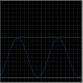
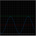
The circuit is working with a single supply, as shown in my simulation.
Why do you think otherwise?
Of course the op amps have to be single-supply types.
 

MrAl

Joined Jun 17, 2014
13,709
Due to its high open-loop gain, an op amp always tries to maintain the differential voltage across its two inputs very near zero.
If you look at your bottom circuit, you can see that the only way for that to occur is if there is no current through R2 and R3, which is only when the output voltage equals the input voltage, hence is is operating as a follower
I dont see any gain factor.
 

crutschow

Joined Mar 14, 2008
38,529
I dont see any gain factor.
I assume you are referring to the circuit gain factor(?).

If the idealized op amp input zero voltage difference conditions are only satisfied when the output voltage is equal to the input voltage, than I would think it's obvious that the circuit gain is +1 (a follower circuit).
The supply has to be higher than the output though.
Of course, although only slightly higher if the op amp is a rail-rail type.
 

Thread Starter

Dritech

Joined Sep 21, 2011
907
Still cannot understand what I mentioned in post #32.
Is it correct to say when Vin is lower than Vs/2, U1:2 outputs 2.5V to the + input of U1:A and the input voltage coming from R1 is over-come by this voltage, hence the voltage remains 2.5V ?

1587928762499.png
 

crutschow

Joined Mar 14, 2008
38,529
Is it correct to say when Vin is lower than Vs/2, U1:2 outputs 2.5V to the + input of U1:A and the input voltage coming from R1 is over-come by this voltage, hence the voltage remains 2.5V ?
Yes, but I think it's clearer to say that U2 clamps the voltage to 2.5V through D2, not outputs 2.5V (since technically it's outputting about 3.2V).
 

MrAl

Joined Jun 17, 2014
13,709
Still cannot understand what I mentioned in post #32.
Is it correct to say when Vin is lower than Vs/2, U1:2 outputs 2.5V to the + input of U1:A and the input voltage coming from R1 is over-come by this voltage, hence the voltage remains 2.5V ?

View attachment 205473
Hi,

Not entirely sure where you are getting this 2.5v from or what you are doing but here is a drawing that shows how to use superposition to calculate the entire output voltage for all time.

To do this the circuit is broken down into three sub circuits and the output comes from all three. The top circuit is for when the input is negative, the bottom two and the resulting third one on the right are for when the input is positive. Since you know how an inverting and a non inverting op amp circuit work this might help because the bottom two use those to calculate the output voltage.
The input voltage for this display is just 1v peak AC so the output has a peak of 1v also.
Note that when the bottom op amp of the original circuit is clamping, the ground symbol in the equivalent circuits diagram shows a heavy ground symbol that is filled in. The other heavy ground symbols are just for use when calculating the outputs using superposition.

Another caveat is the frequency response will be limited because it looks like the bottom op amp goes out of the linear range. If so, the slew rate gets longer in many cases so i'd have to check that. it could cause massive distortion on the output if it changes too much. This is true with some precision rectifier circuits.
 

Attachments

Top