Powerered speakers, power on delay circuit help.

Thread Starter

dougalere

Joined Mar 4, 2015
128
(this is related to an earlier post, for which i apologise , big thank you to #12)
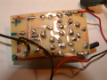
i have built this circuit to replace an existing circuit which we thought was faulty.upload_2016-8-26_17-36-13.png
unfortunately i am getting no delay on this circuit either, just a constant 7.2 volt relative to ground at the output,with no load.,
i am using two 9 volt batteries for testing, giving +9.3volts on the + 15 rail and -9volt on the -15 rail
could someone kindly take a look to see where im going wrong,
i have double checked all componants and paths.
strangely, with no power to the positive rail, im getting 5.4 volts at the zener output.
 

Thread Starter

dougalere

Joined Mar 4, 2015
128
HI
ive only a multimeter, which is why i opted for building a duplicate circuit,
i was thinking of trying this on live wire .any thoughts on this.

this is the circuit -a bit crude broadly following the schematic- cant see anything obvious.
upload_2016-8-26_19-30-37.png
 

Thread Starter

dougalere

Joined Mar 4, 2015
128
just occurred to me, i havent tried turning on all power simultaneously,
i'll see if ive got a three gang switch in my bits box.
 

JoeJester

Joined Apr 26, 2005
4,390
On the printed layout, Identify your parts and their value.

Take an individual pic of your layout, the top of the board, and the bottom of the board.

When you test the delay, and remember, it's about one second, you need to be watching the meter as you energize the circuit.

What is the resistive load on the zener's output? What are the two voltages are you applying?

It occurred to me the circuit is designed to work with plus and minus 15V (14.3V) and you won't get satisfactory results with plus and minus 9V.

You can go back to the original circuit and take some voltages at each element, then post those and the members can help you troubleshoot the circuit.

If you just want to change the time the mute is ON, all you need to do is change one component. But let's see if it's operating normally before jumping into that.
 

Thread Starter

dougalere

Joined Mar 4, 2015
128
i should power the circuit from the speaker rails, but i didnt want to risk damaging the speaker power supply stuff.until the new circuit was tested and working.
re your third point, the zener output feeds into a RC network before it reaches the amp chip,.http://music-electronics-forum.com/attachments/33751d1430277257-svparts_rp6g2scha1.pdf
scroll to bottom.
i could copy and paste this rc circuit but could there be copyright issues?.
i have built this circuit as well, but i havent yet connected it up.

A bit worrying ,if it needs this section connecting in order to work, then the (presumed) delay circuit of original post might well be ok...
 
Last edited:

JoeJester

Joined Apr 26, 2005
4,390
A bit worrying ,if it needs this section connecting in order to work, then the (presumed) delay circuit of original post might well be ok...
I think you should troubleshoot the original circuit vice redesigning a new one. That is my opinion. What model is your multimeter?

I'll be back after my tournament. Let me know which way you want to go. If you just want to mute the circuit a longer period of time, that's fine.
 

Thread Starter

dougalere

Joined Mar 4, 2015
128
thanks joe
re your points
, there is no delay to extend ,hence the speaker pops on power on..

the original delay circuits are not easy to follow, being mixed up with other circuits,and with with plenty of pitch type gunge applied to the boards by the manufacturer, not to mention the wrong schematic.
i would like to persevere with my new circuits, as they are easy to follow ,well spaced,and the componants are brand new , and there is no risk of damaging the original amplifier boards by what would
be tricky diagnostics..
regards
doug
 

absf

Joined Dec 29, 2010
1,968
I simulated your circuit with proteus and it doesn't seem to work with 2x 9V battery. But it does give 9V on the output with +/- 15V....

screen shot4B-9.PNG
screen shot4A-15.PNG
Allen

p/s my simulator doesn't have the 4580, C1815 & A1015. The 4580 is a common R2R opamp used in Yamaha keyboards.
 
Last edited:

JoeJester

Joined Apr 26, 2005
4,390
The reason it doesn't work with 9 volts is the PNP transistor isn't being switched ON.

Change that 1k to 1.5k or something larger to place the PNP into saturation. Then it will work with nine volt supplies and 15 volt supplies.
 

Attachments

Thread Starter

dougalere

Joined Mar 4, 2015
128
joe
i appreciate the time youve put in on this, i did try a quick simulation on livewire with an incandescant bulb as a load, and i think, 15 volt supplies, but i couldnt get it to light,
live wire is a bit basic but it does have an oscilloscope,
i have proteous but i dont know if it has the simulator..
i am adding the audio chip R/C circuit as i type .using a voltmeter.on the output.
will let you know what happens.
i must be mad, its 4 in the morning here,
by the way this is the audio chip--
i dont know what the standby pin does.
thanks again
doug
upload_2016-8-28_4-1-5.png
 
Last edited:

Thread Starter

dougalere

Joined Mar 4, 2015
128
thats interesting,( i havent changed the pnp resistor yet)added the audio chip input rc circuit,with both batteries connected ,its reading zero, zilch, nothing,on the output.relative to ground.
but a constant 2.54 volts when i disconnect the negative 9 volt battery..
which i think is close to the recomended voltage on pin 10...allowing for the lower rail voltages,
could it be that mute is disabled with power on- ,the opposite to how a relay would work.?
dont know if that makes sense to you.
still no delay though,
changing the resistor now,

pin 4 on the chip schematic?
 
Last edited:
Top