Power supply with LM317 Advices Needed - Part 2

Thread Starter

jm-X

Joined Feb 12, 2023
32
Hi all,

I have a few questions - not a lot, like in earlier post ...- about schematic of " Power supply with LM317 Advices needed ".
Many, give me good replies and i appreciate...

Question 1:
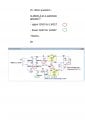
Is there One GND or Two GND?
See Schematic Below.
Ground-Question.jpg

Question 2:

It's about Output Voltage; maybe misunderstanding of KVL:

Output Voltage: 1.25*(1+(5*10³*1.5*10³)/(6.5*10³))/120 = 13.26 V DC Right or False?

Let's say 1.5* 10³=0 U3 in schematic

Output Voltage: 1.25*(1+(5*10³/120)) = 53.33 V Right?????? It seems False....


Question 3:

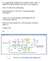
I really searched Google and others means, but stuck with how to get this negative voltage, for 0V LM317 Output:(So, if someone can explain me; would be great.

See image below:
Negative-PS-LM337-Question.png

4° Question:

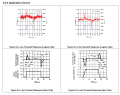
Read in schematic, for improving Line Transient Response:

With 10mF C3 capacitor, ripple current from 4 x MBR735 Bridge, is decreased, but there's still ripple after LM317?

In short, can I add D1, C2, C3, or C4 100µF is sufficient to get a low LM317 ripple output?
Application-Curves-Line-Transient-Response.png

Improve-Ripple-Circuit-Schematic.png


5° question: :)

Thanks a lot and nice day too.

jm
 

AnalogKid

Joined Aug 1, 2013
12,238
Question 1: There is only one GND for the circuit. The red and green GNDs are all connected together.

Question 3 - Those components form a charge pump. This picks off some AC from the transformer secondary, and converts it to a negative DC voltage. This is necessary for an LM317 circuit to adjust down to 0 V. The negative voltage is not well regulated and has some ripple, but the 337 reference circuit handles this.

https://en.wikipedia.org/wiki/Charge_pump

ak
 

crutschow

Joined Mar 14, 2008
38,672
Question 1
Is there One GND or Two GND?
In any schematic, all nodes with the same GND symbol are connected together.
Why would you think they are different?
If the grounds were different, then their symbols would be different.

Question 2:
It's about Output Voltage; maybe misunderstanding of KVL:
Apparently.
KVL equations can make the calculations more difficult then they need to be for some circuit configurations.
For those cases, doing the calculation using the current through the circuit can be simpler.
For example, it can be handy when doing the calculation for a multiple-resistor resistive divider.

The LM317 maintains a voltage of +1.25V from the OUT to the ADJ terminal when in regulation, thus there is a constant current of 1.25V/120Ω = 10.4mA through R2.
This means there is always 10.4mA flowing through the parallel combination of R1 and U3.
Also the LM337 maintains a voltage of -1.25V at its output.
So the output voltage is 1.25V + 10.4ma*(R1||U3) - 1.25V, (where R1||U3 is the resistance of R1 and U3 in parallel).
Thus when U3 is zero resistance, the output is 0V.

Question 3:
how to get this negative voltage, for 0V LM317 Output.
Node 2 is going between the pk-pk AC voltage and zero due to the action of D4.
When node 2 goes positive, current flows through C2 the D5 to ground, charging C2 to the positive peak voltage.
When node 2 goes back towards zero, the voltage at D5 now goes negative from the charge on C2 .
Since that is blocked by D5, current then flows through D6 to charge C1 to the negative voltage.
When the node 2 voltage goes back towards positive, D6 blocks any reverse flow, and C1 stays charged at the negative voltage.
This happens every AC cycle to keep C1 charged at near the negative pk-pk transformer voltage minus the forward voltage-drop of D5 and D6.

Question 4:
With 10mF C3 capacitor, ripple current from 4 x MBR735 Bridge, is decreased, but there's still ripple after LM317?

In short, can I add D1, C2, C3, or C4 100µF is sufficient to get a low LM317 ripple output?
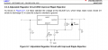
The active regulator circuit in the LM317 has an inherent high ripple-rejection, so the output will have only a very small ripple from the rectifier input ripple across C3.
With C4, this ripple rejection is about -80dB (1e-4).


.
 
Last edited:

Thread Starter

jm-X

Joined Feb 12, 2023
32
Question 1: There is only one GND for the circuit. The red and green GNDs are all connected together.

Question 3 - Those components form a charge pump. This picks off some AC from the transformer secondary, and converts it to a negative DC voltage. This is necessary for an LM317 circuit to adjust down to 0 V. The negative voltage is not well regulated and has some ripple, but the 337 reference circuit handles this.

https://en.wikipedia.org/wiki/Charge_pump

ak

Hi AnalogKid,

Thanks you also for your reply.

Nice day for you and, all AAC members, as well.

jm
 

crutschow

Joined Mar 14, 2008
38,672
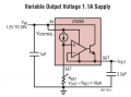
I like the LT3080
I do too, for a regulator that can be adjusted down to 0V output.
But it's about 10 times as expensive as the common LM317.

For your amusement, here's a reasonably simple circuit using the old LM723 regulator to provide 3A that can be adjusted to 0V output:
It connects the 7V Vref voltage to the adjustment potentiometer U2 to cancel out the Inv reference voltage (2V here) when the pot wiper is at 0% (top), giving a 0V output.

1786997862412.png
 
Last edited:

crutschow

Joined Mar 14, 2008
38,672
Am I the only one that's a bit bothered by orienting C1 so that it has reverse polarity?
Yes, that could be an issue.
Depends upon how much a typical electrolytic will be bothered by 1.25V reverse volage.
Google AI says they can tolerate between 1 to 1.5V reverse voltage.

The capacitor could be eliminated, but with some increase in the output ripple voltage.

Another solution would be to connect the (-) capacitor terminal to the LM317 output with an added electrolytic from the LM317 output (-) to ground.

And a third is to use two 200µF electrolytics back-to-back.
 
Last edited:
Top