power supply using lm317

Thread Starter

Syed Naqvi 7

Joined Oct 14, 2015
14
Assalam o alaikum...
Friends...how are all of you?
I am implementing variable power supply circuit o multisim but i ain't getting the perfect output...
please help me out of this problem...
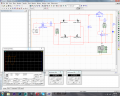
44.073V is output voltage of transformer and 27.408V is regulated voltage when pot is set to 0%, but see the wave of transformer. Its negative wave is chopped...
and another problem is maximum regulated voltage should be 37V but it is 27.44V

upload_2016-4-2_19-44-21.png
 

bertus

Joined Apr 5, 2008
22,270
Hello,

Is there a buffer capacitor in front of the regulator?
I only see an 100 nF capacitor between the diodes and the regulator.

Bertus
 

Tonyr1084

Joined Sep 24, 2015
7,852
Your negative wave form (channel B) is chopped because you're reading AC (lets call it the plus side) and ground through D4. When the waveform goes negative it's being blocked by D4.

That and what others have said about the size of your filter cap (C1) being Nano Farad versus Micro Farad (nF vs µF). I also like the idea of adding a load to the output to verify how well the regulator will function.
 

AnalogKid

Joined Aug 1, 2013
10,986
Scope channel 2 is AC coupled, which is why the display is displaced. Please change the color of one of the scope traces and indicate which waveform is which input.

ak
 

bertus

Joined Apr 5, 2008
22,270
Hello,

C2 is NOT a buffer capacitor.
Put a capacitor of 1000 - 5000 μF parallel to the C1 and make C1 100 nF.
Also put a capacitor of 1 μF on the output of the regulator:

LM317_voltage_regulator_schematic.png

Bertus
 

Alec_t

Joined Sep 17, 2013
14,280
I don't know how 'scopes work in Multisim. It looks as if both channels are referenced to ground in the pic, but the 'scope would need to be in differential mode to measure the voltage directly across the transformer.
 

Jony130

Joined Feb 17, 2009
5,487
It looks as if both channels are referenced to ground in the pic
It's even worse, the scope is "floating" because this "scope" has a common GND . This "G" pin in the upper right corner is a GND and us we can see this pin is "floating".
 

Tonyr1084

Joined Sep 24, 2015
7,852
Originally (first post) you had C1 and C2 in their proper places, albeit the wrong values. In your second diagram you removed C2 (don't know why, but you shouldn't have). In the latest diagram you moved C2 in series with the output of the transformer. I REALLY don't know why you did that - there is no DC to be blocked, so C2 being there is pointless.

You have XMM2 correctly wired. The scope (channel B) must be wired exactly the same way in order to read the sign wave properly. Using the common ground forces the scope to see the sign wave through D4 (as stated before in a previous post). Your sign wave is NOT going to look proper when you read through a diode. Depending on what kind of diode you specified in your "Virtual Diode (D1 - D4)" your wave form will be affected. Not all diodes are created equal. Different forward and reverse blocking characteristics, some are schottky, some are zener. Since we don't know what you used we can't troubleshoot your circuit.

Go back to the first schematic. Change C1 to a 1000 µF capacitor. C2 can be a 0.1µF or even a 1.0µF cap. C2's value is not so critical, but is good to be there to help smooth out the waveform of the output. Keep the LED load.

As for the sim scope - it needs to be wired in the same way as XMM2. XMM2 is reading 41.345 VAC. Not sure if that's RMS value, but your scope (channel B) is set to 20 V per division, so it looks like it's reading properly, 58.742 VAC. Multiply the RMS value by 1.414 to get P to P (Peak to Peak) and you can see the scope is reading properly (as far as voltage is concerned). The capacitor you placed in series - I don't know how that is affecting the wave form but again, channel B needs to be across the output of the transformer like crutschow said in post #6. Otherwise you're reading one half of the transformer through D4. You MUST correct these things before you're going to get the proper reading.
 

Tonyr1084

Joined Sep 24, 2015
7,852
See if this clears things up for you:

TP (Test Points) 1 & 2 are your 220 VAC input. The input is read as an RMS voltage (Root Mean Square), NOT P to P (Peak to Peak). TP 3&4 are your output from the transformer and are 41.345 VAC RMS. The P to P (or PP) value is 58.742 VAC PP. Your meter will read the RMS value while the scope will display the PP value. If you're being confused by seeing nearly 60 VAC PP on the scope - don't be. That's what it should look like.

TP 5 to 7 show the rectified voltage. You're getting close to the PP value because C1 is storing up to the PP voltage. Thus, you get nearly 58.742 VDC. Remember, it's been rectified and will be slightly lower than the AC PP value. The reason is the voltage drop through the diodes (the bridge rectifier). TP 6&7 are your regulated output test points.

Instead of using a two channel scope - try a single channel. Set it to DC coupling and connect it to TP 3&4. Just like Crutschow has said a number of times before - you WILL get a pure sign wave. NEXT, connect the scope to TP 5&7 You will see the PP value close to a straight line. You should see some ripple because the rest of the circuit is drawing down C1. C1 is your input buffer. C2 is your output buffer. C1 stabilizes the incoming signal from the AC ripple and C2 stabilizes the output making up for sudden spikes in the drain current of your load (the LED). It stops transient spikes from affecting components further down the line.

Put your meter XMM1 on the output (TP 6&7) and adjust the value of RP1 (Potentiometer) to the desired output of your circuit. This WILL work. You WILL see the sign wave as expected on 3&4. You WILL see 58.742 VAC PP. Your regulator will see approximately 58.742 VAC DC. Your output will be what you set it to be.

REG PS LM317.png

[edit] Slight correction on my drawing: TP 3&4 voltage is not "58.742 volts Peak to Peak" it's "58.742 Peak Volts" (one side of the sine wave). RMS is also one side of the wave form. In other words you have a 41.543 (corrected value) volt wave form (RMS).
 
Last edited:

crutschow

Joined Mar 14, 2008
34,280
It's even worse, the scope is "floating" because this "scope" has a common GND . This "G" pin in the upper right corner is a GND and us we can see this pin is "floating".
I believe if that pin is left open the scope GND is connected to circuit ground.
So it's okay to leave it floating as long as you understand that.
 

dannyf

Joined Sep 13, 2015
2,197
Still i'm not getting the correct input wave....
your rectifier section doesn't have a ground. and your output as set by the pot is too high for the input voltage. Fixed them and you have a starting point.

AC-coupled probes are not your problem and can be perfectly valid, for ripple measurements for example.
 

Tonyr1084

Joined Sep 24, 2015
7,852
DC coupling will show the true voltage whereas AC coupling will only show the variance of the sign wave. Below is a paintbrush example of what that would look like.

Notice the grid on the top (the DC coupled) shows 10 volt divisions above zero whereas the grid on the bottom (the AC coupled) shows ZERO volts in the center with FIVE volts Positive and FIVE volts Negative.

The AC coupled trace shows Two volts above and below Zero. Whereas the DC coupled trace shows a variation from Three volts positive to Seven volts positive. There IS a difference between setting for AC coupling and DC coupling.

AC vs DC Coupling.png

Use AC coupling when you want to measure a sign wave while eliminating any possible DC voltages that would otherwise interfere with the signal.
 
Last edited:
Top