Facebook
 Google
 GitHub
 Linkedin
Hi,
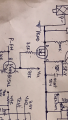
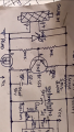
I am trying to design solar charge controller. Can anyone tell me whether to provide power to microcontroller and other IC, through solar panel or through battery.
I got stuck as If we provide power through solar panel, then how microcontroller will get power during night and if we provide power through 12 volt battery then obviously circuit won't work if battery voltage goes down to 10 volt or less. (INA138 current sensor requires minimum 10 volt to work).
NOTE: Ground for panel and battery is not same. Both the ground are separated by MOSFET switch as MOSFET works as a PANEL reverse current protection.
Can anyone help me on this???