Power supply problem

Thread Starter

cat3rn

Joined Jun 3, 2008
117
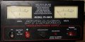
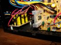
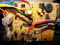
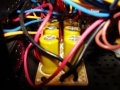
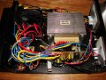
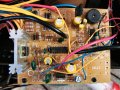
I have (had) a pyramid power supply 35 amp and have used it on my hydrogen cell numerous times. One day the fuse blew. I replaced the fuse only to have it blow again. I have replaced the mosfets and still fuse blows. I am not sure why. Can someone help me out it repairing this power supply?
 

thatoneguy

Joined Feb 19, 2009
6,359
Main issues with that model seem to be the fan dying. Overall, Pyramid doesn't have the greatest reviews, their cost is the only saving factor.

You are also running it at max capacity, which isn't good for power supplies. For a 35A load, you should get a 50A or larger power supply.

Finally, which MOSFETs did you replace?!?? That might be a problem.

Just the same, here's the schematic extracted out of the PDF:


Attachments

thatoneguy

Joined Feb 19, 2009
6,359
First questions:

Is the "Protection" Light on?
Is there any voltage/current displayed on the meters with load connected or disconnected?
How long was it turned on before the fuse blew?
What is the part number of the output transistors you replaced?

Might want to check around the protection circuit, it is a [SIZE=-1] TYN410 SCR, which is only rated for 10A. Also check the zener that triggers it (overvoltage circuit).

Also check Q1, the TIP41C on it's own heatsink on the board. Both it and the SCR have slight discoloration of the heatsink tab rough corners (maybe).

If you can unmount the circuit board and get a good, clear picture of the bottom, that will give a lot of insight towards any overheating. Solder joints will be 'greyish' and the solder mask itself changes color with high heat.

[/SIZE]Caps look good from what I can see, make sure they aren't leaky if you have the equipment.
 

studiot

Joined Nov 9, 2007
4,998
Personally I'd ask myself if the fuse keeps blowing is it because the crowbar circuit (SCR) keeps activating for some reason.

Another possibility would be shorted turns on the transformer. Are the TX voltages correct?
 

Thread Starter

cat3rn

Joined Jun 3, 2008
117
Main issues with that model seem to be the fan dying. Overall, Pyramid doesn't have the greatest reviews, their cost is the only saving factor.

You are also running it at max capacity, which isn't good for power supplies. For a 35A load, you should get a 50A or larger power supply.

Finally, which MOSFETs did you replace?!?? That might be a problem.

Just the same, here's the schematic extracted out of the PDF:
I just tested the fan and it runs fine. I was only running the PS at 20 amps.

Sorry not the mosfets but the Bridge Rectifiers were replaced.

http://search.digikey.com/scripts/DkSearch/dksus.dll?Detail&name=GBPC3501-E4/51GI-ND
 

thatoneguy

Joined Feb 19, 2009
6,359
First: What was wrong with the bridge rectifier you replaced? If it failed short, there could be a whole slew of problems.

Per Studiot's idea:
Measure the resistance of the transformer primary WHILE IT IS NOT PLUGGED INTO THE WALL.

Do the same for the secondary, the diodes should prevent an incorrect reading from other components.

Make sure the Collector-Emitter is not a short for any of the power transistors.
 

Thread Starter

cat3rn

Joined Jun 3, 2008
117
First questions: Is the "Protection" Light on?
No lights are on.

Is there any voltage/current displayed on the meters with load connected or disconnected?
Answered

How long was it turned on before the fuse blew?
I used it for about 3 weeks and had it on that time for about 30 min.

What is the part number of the output transistors you replaced?
Earlier answer link to digikey.

Might want to check around the protection circuit, it is a TYN410 SCR, which is only rated for 10A. Also check the zener that triggers it (overvoltage circuit).
Also check Q1, the TIP41C on it's own heatsink on the board. Both it and the SCR have slight discoloration of the heatsink tab rough corners (maybe).
How do I check these? I have a meter with the diode check on it. I get 513 with the position a and it counts up to 1.999 then changes to a 1 in the b position. Using this as a guide.http://www.allaboutcircuits.com/vol_3/chpt_3/2.html

If you can unmount the circuit board and get a good, clear picture of the bottom, that will give a lot of insight towards any overheating. Solder joints will be 'greyish' and the solder mask itself changes color with high heat.
Attached

Caps look good from what I can see, make sure they aren't leaky if you have the equipment.
I dont own an ESR meter. I am trying to make the Blue ESR from
http://www.anatekcorp.com/blueesr.htm
 

Thread Starter

cat3rn

Joined Jun 3, 2008
117
First: What was wrong with the bridge rectifier you replaced? If it failed short, there could be a whole slew of problems.
They where inexpensive and it was suggested that they might be the problem and they were easy to replace so I did and didn't check them out.

Per Studiot's idea:
Measure the resistance of the transformer primary WHILE IT IS NOT PLUGGED INTO THE WALL.
Duh (not plugged in lol) but will do that and post the numbers.

Do the same for the secondary, the diodes should prevent an incorrect reading from other components.
OK

Make sure the Collector-Emitter is not a short for any of the power transistors.
Where is this located and what is it. Not a genius here but pretty smart.
 

thatoneguy

Joined Feb 19, 2009
6,359
Didn't see pic/attachment for bottom of circuit board.

Look at the datasheet for the transistors. Often the case is the collector, one pin is emitter, the other is base on a TO-3.

If the bridge rectifier you replaced tested good (4 good diodes), then the negative input isn't a concern.

If it took 30 minutes for the fuse to blow, it isn't a short, but a "big leak". Did the power supply function correctly while the fuse was good? Did it have voltage/current oddities right before it blew? Did the Voltage adjust need to be changed from "normal position" recently? Anything "Smell hot"?

I'll be back in a while....

--ETA: For the "NOT PLUGGED INTO THE WALL" Part is for people who find this site via google and try doing the tests. Too many people like to sue these days.
 

Thread Starter

cat3rn

Joined Jun 3, 2008
117
Didn't see pic/attachment for bottom of circuit board.--ETA: For the "NOT PLUGGED INTO THE WALL" Part is for people who find this site via google and try doing the tests. Too many people like to sue these days.
Sorry forgot to attach it.

I know about that. Too many paeople make a living suing.

Also attached is a better pic of the circuit board front.
 

Attachments

Last edited:

studiot

Joined Nov 9, 2007
4,998
You are trying to fault find in a highly inefficient way.

Let's try a systematic approach.

Does the fault occur with little or no load?

If not the fault cannot be due to excessive load now (though may be originally).

Measure the transformer voltages (not resistances).

Are they as expected?

Move on to the rectifier voltages.
If possible disconnect the smoothing capacitors so you are only measuring the TX and then the rectifier voltages.

Are they as expected?

Reconnect the caps & measure the voltages.

Are they as expected?

If all is hunky-dory here then the fault is in the subsequent circuitry.
 

Thread Starter

cat3rn

Joined Jun 3, 2008
117
You are trying to fault find in a highly inefficient way.

Let's try a systematic approach.

Does the fault occur with little or no load?
No load whatsoever.

If not the fault cannot be due to excessive load now (though may be originally).

Measure the transformer voltages (not resistances).

Are they as expected?
Cant measure voltages if I can get it to turn on. Nothing gets past the fuse which is connected to the switch.
 
Top