Power supply problem diagnosis

Thread Starter

wayneh

Joined Sep 9, 2010
17,498
In another thread I'm working on a TV digital-to-analog converter. This thread is more generally about the power supply to such a device. I think mine has a problem.

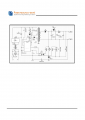
The onboard switching supply is the high voltage area on the right. The big cap is rated to 400V and has ~170V on it. The white jumper far right is the AC 120V input from the wall.

Here's my question about those 5 components in the middle of the back edge. All but the inductor have 5.0V DC across them, including the diode, and 10.0V AC. I also see 10V AC on those empty pads to the right of the diode. All voltages measured with my cheap HF meter.

Those readings don't make sense to me. Isn't 5V DC across a diode a bad sign? And 10V AC on the electrolytics?
IMG_2970.png
 

AlbertHall

Joined Jun 4, 2014
12,346
5V DC sounds like a very likely voltage to find there.
What is the voltage rating of those electrolytics?
What are you measuring the 10V AC with? What is an 'HF' meter?
 

Thread Starter

wayneh

Joined Sep 9, 2010
17,498
5V DC sounds like a very likely voltage to find there.
What is the voltage rating of those electrolytics?
What are you measuring the 10V AC with? What is an 'HF' meter?
The electrolytics are rated, left to right and small to large, 16V, 10V, 16V.

HF = Harbor Freight = Cen-Tech meter
 
Last edited:

AlbertHall

Joined Jun 4, 2014
12,346
I think I would believe the DC readings and disregard the AC readings.
That being so, there is no obvious fault here, unless the 5V is supposed to 9V but we have no way of knowing that and 5V is such a common supply voltage.
 

Thread Starter

wayneh

Joined Sep 9, 2010
17,498
Is the supply working? & what is the number on the switching chip?
See post 1 for symptoms. It's working in the sense that it's passing power. But those AC voltages made me wonder about noise. And how can there be an apparent 5V DC across that diode?

I'm away from the device. I'll see if I can read the IC later.
 

AlbertHall

Joined Jun 4, 2014
12,346
And how can there be an apparent 5V DC across that diode?
Presumably it is a rectifier diode and on the half cycle where it is forward biased the voltage will be very low but on the other half cycle there will be some voltage and your meter will average that out to give some voltage reading.
 

Thread Starter

wayneh

Joined Sep 9, 2010
17,498
Presumably it is a rectifier diode and on the half cycle where it is forward biased the voltage will be very low but on the other half cycle there will be some voltage and your meter will average that out to give some voltage reading.
I wrote about the diode on the way to the pool. As soon as I hit the water I realized how stupid I was. The voltage on the diode is reverse biased, and a little higher in the reverse direction than in the forward direction. Makes perfect sense.

Unfortunately that means I have no leads to follow in repairing this thing.

Here's the power supply detailed pic. It's data sheet is available here.
IMG_2973.png
 

debe

Joined Sep 21, 2010
1,390
Its a pretty simple half wave circuit. Its either ok, or the diode is leaky, or the capacitors are faulty? I would try replacing them & see what happens.
 

Thread Starter

wayneh

Joined Sep 9, 2010
17,498
What makes you think that this PSU is faulty?
I know your question is directed to @debe, but I no longer think there is anything wrong with the power supply, and that means I'm at a dead end. Everything else on this PCB is tiny surface mount stuff with scads of tiny pins. I have no service manual or any reasonable way to proceed.

My only reason for suspecting the PS in the first place was the 10V AC voltage I saw on the DC side. But that could be an artifact of the switching waveform, right?
 
Top