Facebook
 Google
 GitHub
 Linkedin
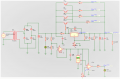
Hello guys, I'm doing a mini project, and the objective is to make a small linear source (24V / 1.5A maximum) using a regulator (LM317) but I was dealing with a problem, my power dissipation at wrost (in LM317) if I am correct, its something like 46.48 watts (P = 32.5V - 1.25V) x 1.5A = 46.48 watts, so its extremly hard to LM317 hold that power dissipation, a huge huge heatsink will be needed, I tried to reduce it by dividing the current through 2 darlington transistores, what would reduce the dissipation, I want to know what do you think about this (I'm new in this game dont blame me  ) ty everyone.
Questions:
How can I make a current limiter until 1.5A?
And what is the power dissipation in R1 and R4?
View attachment 208311
) ty everyone. Questions:
How can I make a current limiter until 1.5A?
And what is the power dissipation in R1 and R4?
View attachment 208311