Power supply 5V DC, 10VDC and PWM 10V

Thread Starter

beire

Joined Feb 11, 2016
6
Hello,

I'm really new to electronics (so please bear with me...)
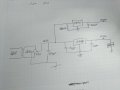
I tried to come up with a circuit (attached) to power an arduino and some other devices.
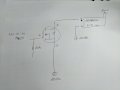
But the main goal is to drive a meanwell lcm-40 ( http://www.mouser.com/ds/2/260/LCM-40-SPEC-806135.pdf )
with the pwm output of an arduino.

I have a mosfet irlz24n n-channel. Can i use this for the pwm 5v to 10v conversion (see attached diagram 2)?

So i'm starting with 230V ac with a transformer to 12v ac i have lying around.
I'm thinking on using a kbl005 rectifier followed by an lm7810 (pwm 10V) and lm7805 (arduino ESP module).
My schematics are just a initial sketch, so very basic.
Can someone point me to any errors (component errors?) or things i should change?

Thanks a lot for any help!
 

Attachments

ScottWang

Joined Aug 23, 2012
7,498
So you trying to using Arduino to generate the pwm signal to drive the leds?
Then how is the specification of leds, and the power of leds is 10V not 12V?
 

Thread Starter

beire

Joined Feb 11, 2016
6
So you trying to using Arduino to generate the pwm signal to drive the leds?
Then how is the specification of leds, and the power of leds is 10V not 12V?
The led's Will be driven by the meanwell driver I linked to. It takes a 10v pwm signal according to the datasheet.

The 10v is just for the pwm signal.
The 5v for the Arduino power.
 

ScottWang

Joined Aug 23, 2012
7,498
The Vgs = 10V of irlz24n N type mosfet, it can be works on 3.3V and 5V, maybe the Vds and Rds will be a little bigger and the Ids will be a little smaller, I hope they don't affecting your applications too much , since you already have the mosfet then you can try it, if the result far from your expecting then we can modify the circuit of Vgs or you go to buy a logical level Vgs as 2.4V ~5V.
 

Thread Starter

beire

Joined Feb 11, 2016
6
I went to buy all parts I still needed today, for the pwm I ended up using a 2n2222 transistor instead of the MOSFET.

I also used the 10v from the 7810 as input for the 7805. I guess it's more economical than starting from 12v?

The circuit runs great actually...

Now do I need some fuses in the circuit?
I guess on the AC supply to the transformer. Also after every voltage regulator output?
What values are appropriate? Since I'm just powering a wemos d1 mini and the pwm signal I'm not using a lot.

I'm measuring 0.3a on the AC side of the transformer.
 

ScottWang

Joined Aug 23, 2012
7,498
I went to buy all parts I still needed today, for the pwm I ended up using a 2n2222 transistor instead of the MOSFET.
You have to make sure how much current the Led needed, the 2N2222 can be provide 800mA, but use it less than 3/800 mA is better.

I also used the 10v from the 7810 as input for the 7805. I guess it's more economical than starting from 12v?
If the 10V is connects from LCM-40 then I don't think it is a good idea, because LCD-40 was designed for the LED dimming, it seems output the current, but does not output for the voltage, when you adjust the DIM+ and DIM- with pot and then the current of +V will be changing according to the pot adjustment.

Now do I need some fuses in the circuit?
I guess on the AC supply to the transformer. Also after every voltage regulator output?
What values are appropriate? Since I'm just powering a wemos d1 mini and the pwm signal I'm not using a lot.

I'm measuring 0.3a on the AC side of the transformer.
A good design always needs the fuse, because you don't know what time the accident will be coming, you can buy some fuses as 0.3A~0.5A to try, start from 0.3A and to see what happens, if it is ok then just use it, otherwise change to another bigger one.
 
Top