Facebook
 Google
 GitHub
 Linkedin

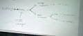
I am a highschooler who has taken interest in electronics and circuits. I have been working on a small Bluetooth speaker for quite some time now. With the little knowledge I have, I scrapped together a working (if I dare say) circuit, however I am redesigning based on how the first prototype went. It was very scratchy and distorted and had a poor maximum volume. The goal with the redesign is to (A) put all components on a PCB board in attempt to decrease resistance and clear up the scratchiness and distortion and (B) properly distribute wattage through the design to make it louder. While trying to draw a schematic for the redesign I realized I don't know proper procedure on how to get the power from the battery to the two amplifiers and computer chips. I attached the schematic to the redesign as well as a little video of my first design here. I would also really like having the modern charging architecture where the device can be used while charging.
I am specifically wondering:
1. How do I figure out what specific parts I need? From my understanding, I will need something to boost the voltage before sending it to the amplifiers as well as something to regulate/boost voltage into the I2S receiver and DAC.
2. Can one boost converter (or whatever would be best fit to increase the voltage) be used for both amplifiers, or do I need one for each? If one can power both, then do I set it to double what is required by the boards in order to supply them both with max power? To me this seems like it would risk sending too much power to one of the boards and might destroy it.
Also, if anybody has advice on designing the PCB or critiques on my current design it would be immensely appreciated.
- The battery is a single 3.7V 2600 mAh Li-ion cell link
- I2S Receiver and Master Clock link
- Amplifiers (2) MAX98357A 2.5-5.5V 4-8hm 3W link
- Speakers 2-3W 8Ohm 200Hz-20kHz link
- I still need to design/pick out parts for a PMIC (I don't really know
what I'm doing here)
- Still need to pick pick out a DAC
I haven't purchased any of the new parts, so I am open to changing parts for the sake of a better design although I do have speakers and amplifiers left over.
Thanks,
Oliver