power inverter proteus simulation

Thread Starter

ahsan ali 3

Joined Aug 18, 2017
19
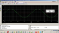
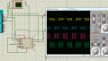
i have made inverter circuit in proteus,have used cd4047 to generate 50hz square wave, i have used irfz44 mosfet. what are the transformer rating for proteus simulation, using a 12V battery, output should be 220 watts, i am confused how to set the step up transformer for proteus.

and if a want to make an inverter of 350 watts, which mosfet shoul i use and what are transformer rating.

i had also posted the inverter schematics.

guide me, your suggestions are valuable for me.
 

Attachments

ArakelTheDragon

Joined Nov 18, 2016
1,362
So you are saying that from a "12V" battery you will drain "220W/12= 20A"?

I dont believe "IC 4047" can supply "20A"?
I think the circuit is wrong to begin with. From "IC 4047" you only make a sine signal, than you amplify this signal with a transistor in order to use whatever power supply you have (12V accumulator battery, solar panel, etc.). You need to amplify the current so you can drain the maximum from the power supply. Whatever you drain from the power supply (220W) must be supported by the transistors, they should have a voltage rating higher than "12V" and current rating higher than "20A", there will be spikes if you dont take measures so the transistors need to be able to take that. Also you will need a radiator for the transistors and preferably use a PWM signal to switch them.

The rating of the transformer = 220W on the first side and 220W on the second one. Also the coils need to be 12V primary and 220V secondary.
 

ArakelTheDragon

Joined Nov 18, 2016
1,362
The greatest problem is to supply a large amount of current to the primary coil of "12V". Your electronics need to be able to do that.

EDIT: Do keep in mind that you will be using "+-12V" effective not amplitude value for the transfomer and on the other side you will have "+-230V" effective value not amplitude value. Amplitude value is the maximum value of the wave (also called the peak) and the effective value needs to be calculated from the maximum normally.

That means that you will have to supply a larger value on the primary coil to get the effective value that you need on the secondary.
 
Last edited:

Thread Starter

ahsan ali 3

Joined Aug 18, 2017
19
So you are saying that from a "12V" battery you will drain "220W/12= 20A"?

I dont believe "IC 4047" can supply "20A"?
I think the circuit is wrong to begin with. From "IC 4047" you only make a sine signal, than you amplify this signal with a transistor in order to use whatever power supply you have (12V accumulator battery, solar panel, etc.). You need to amplify the current so you can drain the maximum from the power supply. Whatever you drain from the power supply (220W) must be supported by the transistors, they should have a voltage rating higher than "12V" and current rating higher than "20A", there will be spikes if you dont take measures so the transistors need to be able to take that. Also you will need a radiator for the transistors and preferably use a PWM signal to switch them.

The rating of the transformer = 220W on the first side and 220W on the second one. Also the coils need to be 12V primary and 220V secondary.
i have mosfets to amplify this signal.......
 

Thread Starter

ahsan ali 3

Joined Aug 18, 2017
19
here i found something...... if i am generating signal from arduino and using a L298,,,,,,will it work........

{{{To use a MOSFET as a switch, you have to have its gate voltage (Vgs) higher than the source. If you connect the gate to the source (Vgs=0) it is turned off.
For example we have a IRFZ44N which is a “standard” MOSFET and only turns on when Vgs=10V – 20V. But usually we try not to push it too hard so 10V-15V is common for Vgs for this type of MOSFET.
However if you want to drive this from an Arduino which is running at 5V, you will need a “logic-level” MOSFET that can be turned on at 5V (Vgs = 5V). For example, the ST STP55NF06L. You should also have a resistor in series with the Arduino output to limit the current, since the gate is highly capacitive and can draw a big instantaneous current when you try to turn it on. Around 220 ohms is a good value}}}


picture for arduino attached


.
 

Attachments

Sensacell

Joined Jun 19, 2012
3,453
The design you have won't scale to 300 W.
Inverters are tricky to design and test, most of the designs floating around on the internet are primitive, or downright bad.
 

ArakelTheDragon

Joined Nov 18, 2016
1,362
Proteus is not recommended for analog designs.

Dont use Arduino.
I dont know about the arduino pins, but a PIC microcontroller should have a "1k: resistor in order to limit the current to "5v/1000=5mA". The maximum current from a PIC microcontroller pin is "25ma", but the recommended one is "5ma-10ma". Check the datasheet for your Arduino if you intend to use.

The principal is this:
You generate a sine signal with a low current and "12V" voltage (perhaps from an MCU). This sine signal must be amplified, where your MOS transistors get in. The amplified sine signal goes to the primary coil and is "300W", "12V", "24A", so the secondary coil will transform "300W", "12V", "24A" into "300W", "230V", about "1A".

The MOS transistors are normally voltage controlled, but you need at the output of the transistors a high current and voltage with sine form. That means you have to apply on the "gate" of the MOS such a signal that you will get on the output a sine again. The MOS transistors are only to amplify the sine signal, however if you have a sine signal on the gate it has to be with "50Hz", in order to get "50Hz" on the output as well, not to mention that you will have to calculate what needs to be the "peak to peak" voltage of the gate sine signal, in order to get "12V" on the drain sine signal.

The MOS transistors in your first circuit were doing exactly this. They were producing a sine signal with "12V" peak to peak amplitude and high current. But I dont think they can withstand "300W".


If you want an easy circuit, I will suggest a driver. The driver will produce a sine wave with "12V", "300W" and will require a sine wave signal with less power on its input.

Or you can do this: use a thyristor, put a sine wave on the thyristor gate and you will get the same sine signal on the output. If you need a higher wattage, connect more than 1 thyristor in parralel. The thyristors, transistors, or whatever you use, need to be able to bare "300W", that means that in the datasheet it has to be said this element can dissipate "300W".

A "H bridge" can also be used as an inverter. But with the "H bridge" 2 transistors take the load and the wattage is halved. On your first circuit, 1 transistor takes the whole wave.

Your MOS transistors will not be able to take "300W" if you dont switch them at a high frequency "10KHz, 20KHz". This becomes modulation and control of the MOS transistors and it becomes very diffuclt. In other words you need to put a sine wave generator of "300W" as the power supply for the transistors's, but you need to switch them on the gate with a "PWM" signal of "10KHz". And that means make the power supply to be a sine wave first, which is not a good idea for such high values.
 

ArakelTheDragon

Joined Nov 18, 2016
1,362
Here is a simple sine wave amplifier with only 1 step of transistors. You need to put 3 steps normally. The first step is 2 transistors working in "class A" for smaller signals like the "12V, 5mA" from the MCU. The second step is in class B, and is a driver circuit which will supply enough current for the last step, and the last step is in class "AB", the one I give you which needs to output "12V, 15A". The maximum of the "2n3055" transistor is "60V, 15A" and can dissipate "115W" under idealistic conditions, lets say that you can get "10A" at best, that is about "120W". You also need a proper PNP transistor, "2n3905" is not good, as it can supply a small collector current. Find a complementary transistor of "2n3055" and make a circuit. After every step, the voltage will drop because the transistors have a "0.6V" losses over the base-emitter junction.

You can provide a sine signal with an MCU or analog circuit (including the one in your first post), amplify the voltage to "36" or "48V", than make a bipolar amplifier with at least 3 steps. "120W/48V = 2A", this is much better for working with. Than make 2 channels of "120W" and you will get what you need. You will never get the full "115W". But you will need a radiator or even a better system with a fan, maybe water to cool this invertor.

If you prefer you can make a power supply with a sine wave "48V, 6A", than use a "H-bridge" with MOS transistors but switch them at "4KHz, 20KHz" so they dont overheat. You will still need a radiator or a fan. It can work with "12V, 25A" but this is the power supply with a sine form and the cooling system will be very high tech! You need to pick your transistors properly. Lets say a bipolar amplifier to get the MCU sine signal to "48V, 2A, 100W", than use this as the power supply for the step up transformer.

Summary - MCU sine signal - bipolar amplifier to "100W", step up transformer.
MCU impulse signal - MOS transistors H bridge gates - power supply for the MOS transistors H bridge at either "12V, 25A" or "48V, 6A".

I never did get where do you take the VDD of "12V" from?
 
Last edited:

bertus

Joined Apr 5, 2008
22,278
Hello,

In your schematic there is no biass for the transistors.
Also there is a great disbalance in the transistors.
The 2N3905 is only 625 mW and the 2N3055 is 115 W.
The complemantairy for the 2N3055 is the 2N2955.

Bertus
 

Attachments

ArakelTheDragon

Joined Nov 18, 2016
1,362
Hello,

In your schematic there is no biass for the transistors.
Also there is a great disbalance in the transistors.
The 2N3905 is only 625 mW and the 2N3055 is 115 W.
The complemantairy for the 2N3055 is the 2N2955.

Bertus
I know I just wrote it on the second, to show the principle. I have noted that in the post that a complementary for "2n3055" is needed.
 

Thread Starter

ahsan ali 3

Joined Aug 18, 2017
19
I know I just wrote it on the second, to show the principle. I have noted that in the post that a complementary for "2n3055" is needed.

thanks, you give much time to my circuit...... but i am giving up...... its very difficult for me to understand too much complicated theory....
its impossible for me to understand without complete schematic and step by step explanation..... but again thanks for commenting ....
 

ArakelTheDragon

Joined Nov 18, 2016
1,362
You are a beginner, I understand, probably a student still.

If you have time and want to do more, here is the principle:
Sine wave - amplified by transistors - given to the primary coil - becomes 230V at the secondary coil.

Whatever wattage you give to the primary coil, the same wattage you will get at the secondary coil, only the voltage will be higher and respectively the current smaller to make up for the power being the same. How you implement the power supply for the primary coil is up to you. Dont go connecting high watages before knowing what you are doing, because like the previous post said, high wattage inverters are tricky. They can have a "2meter" capacitor for power plant inverters. You are doing a micro inverter.

The elements (including the transfomer) need a cooler (if the wattage is high a fan). If you can make the circuits by yourself, you will get what you need. 300W is a lot, start with something smaller, "2W".
 
Top