Facebook
 Google
 GitHub
 Linkedin
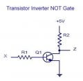
I need some help. I'm trying to calculate the power dissipation of an NPN transistor. I know that the formula is P=VCE x IC + VBE x IB. But in my case all the voltage falls across the collector resistor RC and the collector voltage is 0V. So what is VCE in that case? I know this is inperfect world and that there is some tiny amount of voltage drop across the collector-emitter junction, but what is it?
Power dissipation of transistor
- Thread starter HarrisonG
- Start date