Facebook
 Google
 GitHub
 Linkedin
Hello,
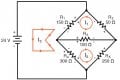
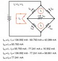
I believe there is an error in the eBook pertaining to the labeling of the direction of current. I am referencing the unbalanced Wheatstone Bridge example. In the circuit diagram the direction of mesh current I3 appears to disagree with the labeled resistor voltage drop polarities. The resistor polarities are oriented opposite of the voltage source but the arrows showing the direction of current infer the resistors are backwards. If the arrows in I3 were reversed it would appear to be correct. This error also affects the latter diagram showing the final direction of currents across each resistor.
Let me know if I am see this right or if it's a misunderstanding on my end.
Diagrams I am referencing are attached.
Thanks.
Attachments
-
 23.9 KB Views: 7
 -
 67.3 KB Views: 7