Positive feedback hysteresis - Do I understand resistor purpose?

Thread Starter

MrJojo

Joined Jan 23, 2013
45
Hello all,

I've been trying to figure out the point of positive feedback for a bit now. I understand that negative feedback is used to stabilize a circuit and positive feedback is used to create basically a comparator. I started off at this post http://forum.allaboutcircuits.com/showpost.php?p=444315&postcount=9. It is a post by Jony310 which he explains what happens when affecting either input terminal and what will happen at the output w/o feedback and then shows what happens when a resistor is used as negative feedback and discusses what happens inside the op amp when said resistor is used w/ neg and pos feedback.

I then started went to the online book from AAC - http://www.allaboutcircuits.com/vol_3/chpt_8/12.html - and checked out the positive feedback section. From here I confirmed that positive feedback is basically a comparator and that you can use a resistor to create a sort of hysteresis. Assume V in is a sine wave from -5 to 5, and the upper limit of the hysteresis is +2 V and lower limit is -2V, then the op amp would remain positive once the voltage in goes about the upper limit (+2V) and remains positive until going below the lower limit (-2V) and rinse and repeat.

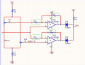
Finally I started looking around for a positive feedback equation where I can use the positive feedback resistor to set my hysteresis - http://forum.allaboutcircuits.com/showpost.php?p=298747&postcount=4 - t_n_k has an equation from that post stating the hysteresis is found by (Voh-Vol)*R14/(R42+R14) These values can be found at the attachment below labeled AAC_help_forum_post.

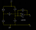
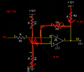
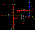
So all that being said, now I present my circuit - which is an example for what I'm actually trying to do and can be found at AAC_help_my_circuit. So the voltage at pin 7 should be ~ 5V and the voltage at pin 6 should be 6V. From that means that the center point is 5V and using the equation from t_n_k (Voh = 10V, Vol =0V), my hysteresis is 10V. So that means the upper limit is 15V and the lower limit is -5V, correct? I understand I can’t reach these values, but this is just an example of something I threw together really quick.
 

Attachments

Thread Starter

MrJojo

Joined Jan 23, 2013
45
Jony130,

First, did I understand your post correctly? I think I did and I was trying to give a brief summation vs a butchering (which I'm hoping I didn't >.<)

I'm trying to figure out a temperature sensing circuit. A bud gave me a circuit he was having troubles with and I said I'd take a look at it. The image I posted is basically the same thing as what he gave me, only the values are changed and there is a pull up resistor at pin2 of the op amp to 12V.

Right now, I'm trying to figure out if I have an understanding of the positive feedback resistor and then what is the true temp range of the actual circuit.

I'm reading up on the open collector page right now.

Matt
 

Thread Starter

MrJojo

Joined Jan 23, 2013
45
Jony310,

Thanks for bringing the open-collector situation to my attention, I know understand why the pull up resistor is there in the first place!

So if I'm understanding the open-collector correctly, does this mean that the IC's output is inverted? I ask because of

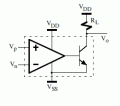
The output usually consists of an external pull-up resistor, which raises the output voltage when the transistor is turned off. When the transistor connected to this resistor is turned on, the output is forced to nearly 0 volts.
Matt
 

Jony130

Joined Feb 17, 2009
5,600
OK I see, I add 1KΩ pull-up resistor. And remove input voltage divider.
For Vin = 0V the voltage at non-inverter input is equal to

\(Vp = Vcc *\frac{(Rp + R5)||R3}{((Rp + R5)||R3) + R4}= 6.26V\)

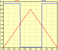
Now let as assume that input voltage ramp up from 0V to 10V
For Vin = 0V and Vp = 6.2V--->Vout ≈ 12V because Vp - Vp > 0 and LM339 output transistor is off.
For Vin > 6.2V the LM339 will turn-on his output transistor and shorts the output to ground. So the new non-inverter voltage is now equal to:
Vp = Vcc* R3/(R3 + R5||R4) = 5.71V. And Vp - Vn < 0 and that's why LM's output transistor is turn on and Vout ≈ 0V
Any further increase in Vin will have no effect on the output (0V at output).
What we can do is to ramp down our Vin.
And again nothing happens until Vin = Vp = 5.71V then again Vp - Vn change the sign and LM339 turn-off his output transistor. And Vout goes to Vout ≈ 12V and Vp change to 6.2V

As you can see we have upper and lower threshold voltage

Vth1 = 6.2V and Vth2 =5.7V

http://www.bristolwatch.com/ele/vc.htm
 

Attachments

Last edited:

MrChips

Joined Oct 2, 2009
35,184
Do not confuse open-collector output and inverted output.
They are two different issues.

The output can be open-collector or non-open-collector.

The output could be inverted or non-inverted.
 

Thread Starter

MrJojo

Joined Jan 23, 2013
45
@MrChips,

I don't know the proper term for what I'm thinking of, but the way my brain has associated open-collector is like a not gate, when there is voltage present at the base, it outputs ground and when there is no voltage present, it outputs Vcc. Is that a generalization or should I just not think like that for the open-collector output?

@Jony310,

I've gotten about half way though the article you linked me and I think I get it, but I'm not 100% positive. so from what I'm gathering, when the + terminal > - terminal, the transistor inside of the LM339 is open and vice versa for - > +. That means when the + > -, the output will go towards the Vcc line due to the pull up resistor. When - > +, the output will go towards ground due to the internal ground from the open-collector transistor, correct?

Matt
 

Jony130

Joined Feb 17, 2009
5,600
@Jony310,

I've gotten about half way though the article you linked me and I think I get it, but I'm not 100% positive. so from what I'm gathering, when the + terminal > - terminal, the transistor inside of the LM339 is open and vice versa for - > +. That means when the + > -, the output will go towards the Vcc line due to the pull up resistor. When - > +, the output will go towards ground due to the internal ground from the open-collector transistor, correct?

Matt
Yes, exactly. But this is nothing new, so you shouldn't be surprised. Because this is how op amp work.
http://forum.allaboutcircuits.com/cache.php?url=http://images.elektroda.net/12_1254347153.png
 

Thread Starter

MrJojo

Joined Jan 23, 2013
45
@Jony130

Yes, agree, but it's strange for me to think that it is all based on the pull up resistor though. I guess that's what is throwing me through the loop along with I never really understood the inside of the op amp - it was like the magic smoke to me. Plus that was to make sure I understood the basic circuit before I ask the following question.

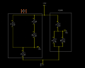
So I tried to draw an equivalent circuit for the op amp under the two conditions. The one on the left is when the + terminal > - terminal. The one on the right is - terminal > + terminal. So at TP1 the equation to solve for that would be
\(Vp = Vcc *\frac{(Rp + R5)||R3}{((Rp + R5)||R3) + R4}= 6.26V\) while at TP2, the equation is Vp = Vcc* R3/(R3 + R5||R4) = 5.71V, correct? That means to me that when +>-, the current flows from the + terminal -> R5 -> Rp -> +12, while ->+ current flows +terminal -> R5 -> GND.

I think I truely understand what is going on in this circuit now, I'm just going into explicit details here to verify my understanding is correct.

Matt
 

Attachments

Jony130

Joined Feb 17, 2009
5,600
@Jony130

Yes, agree, but it's strange for me to think that it is all based on the pull up resistor though. I guess that's what is throwing me through the loop along with I never really understood the inside of the op amp - it was like the magic smoke to me.
At first glance you can treat lm339 as a ordinary op amp plus additional NPN transistor connected to the op amp output.


That means to me that when +>-, the current flows from the + terminal -> R5 -> Rp -> +12, while ->+ current flows +terminal -> R5 -> GND.
Are you sure about that ? Op amp input current is very low. So none current can flow into op amp input terminals.

Current flow like this
 

Attachments

crutschow

Joined Mar 14, 2008
38,820
To clarify, the LM339 input polarity refers to the output with a pull-up resistor. Thus if the (+) input is greater than the (-) input, the output goes high (output transistor is cut off).
 

Thread Starter

MrJojo

Joined Jan 23, 2013
45
@Jony130,

For the case of Vp>Vn, that is what I thought happened, but looking back, I had my direction of current backwards. As for the case of VP<Vn, I didn't account for the Rp. But would that matter? I mean the 1k pull up is basically going to ground so my thoughts are it wouldn't affect the R3||(R4+R5) network.

matt
 

Jony130

Joined Feb 17, 2009
5,600
@Jony130,
As for the case of VP<Vn, I didn't account for the Rp. But would that matter? I mean the 1k pull up is basically going to ground so my thoughts are it wouldn't affect the R3||(R4+R5) network.
Yes, Rp has no effect on Vp voltage.
 

MrChips

Joined Oct 2, 2009
35,184
I don't know the proper term for what I'm thinking of, but the way my brain has associated open-collector is like a not gate, when there is voltage present at the base, it outputs ground and when there is no voltage present, it outputs Vcc. Is that a generalization or should I just not think like that for the open-collector output?
It may be true that the open-collector output is implemented with a common emitter BJT as you have described. The consequence is that the logic output at the collector is reversed from that at gate. That is because the common emitter BJT configuration is an inverting amplifier. So the BJT performs a logical NOT function.

But all of that should be of no concern when discussing the operation of an analog comparator with open-collector output.

What you need to know is, when the voltage at the +ve input exceeds the voltage at the -ve input, is the output logic LOW or HIGH. For the correct answer you have to look up the datasheet.
 
Top