Polyester Film Capacitor

Thread Starter

spike1947

Joined Feb 4, 2016
537
Hi Guys again !

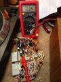
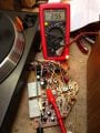
I am trying to do the adjustments has per page 11 of the Service Manual, the problem I have is that it is saying ( Motor Gain Adjustment) Item .1.Turn the switch to H1 position and adjust RV2 for 2.3v ac reading, and the same for Item .2., but there is no switch there ! .

cheers
Spike
 

Attachments

Ian0

Joined Aug 7, 2020
13,132
Is the little bit of circuitry with two diodes, two resistors and two caps actually part of the turntable? It has no component ID numbers. Or is it something you are supposed to make in order to do the tests?
 

Thread Starter

spike1947

Joined Feb 4, 2016
537
Is the little bit of circuitry with two diodes, two resistors and two caps actually part of the turntable? It has no component ID numbers. Or is it something you are supposed to make in order to do the tests?
That is only for the Offset Adjustment !, not for the Motor Gain Adjustment, but still I can not find a Switch in the location were the drawing says it is ! .

Spike
 

Ian0

Joined Aug 7, 2020
13,132
My guess is that it means "connect your voltmeter to pin 3 of the socket" or "connect your voltmeter to pin 4 of the socket" and set RV2/3 for 2.3V AC. I think it's a virtual switch!
 

Thread Starter

spike1947

Joined Feb 4, 2016
537
Agreed about the capacitor. It will still work without it.
Is there power to BOTH windings on the motor? It's a synchronous motor, so it will run on one winding once it has started.
Hi
Where do I take the measurements for the 2 winding's !
Spike
A low value capacitor would not be tested the same as electrolytic capacitors, it it were, the results would be totally different. The value is far different and the type is totally different.
What I think I see is that the label on the board calls that capacitor "CP1", an encapsulated component, and elsewhere as a mylar capacitor. And it is connected across the power switch, explaining the AC rating.
No matter if a capacitor in that position was open or shorted or leaky, the running would not be affected by it. So probably that capacitor is OK, and the problem is elsewhere. So since the motor runs when given a push start, check the power supply voltages, since the symptom is not quite enough torque. It may also be that the power switch has failed. The manual gives a lot of assistance and so reading it is a good start.
Randomly checking components is a terribly inefficient way to do trouble shooting and seldom produces results in the first few hundred checks.
Since the turn table drive motor runs it is reasonable that most of the parts are OK, and that ALL of the critical parts are at least close to OK. So then you need to consider what it does not do, which is start by itself. That points towards either a weak starting circuit or else just not quite enough torque. It might even be from poor lubrication in a bearing causing excessive drag.
Hi again
Just had the Cap in question tested by a friend and He said that it is ok and the 2x Elec ones are also ok, so have soldered them back .
Question: Where about's is the "Starting Circuit" located?.

Have been trying to do some adjustments for the voltage's as per page 11, " Motor Gain Adjustment " , but am stuck on were it says " Turn Switch to H1 position, can't find a switch in the position that the drawing says ! , please excuse me for asking all these questions as I am a total novice when it comes to fault finding on these type of gear, but it is a Turntable that I have had a long time and it has been a very good one ( up to now ) so I am just trying everything I can think of before having to send it to the tip (dread the thought ) .

Cheers
Spike
 

Thread Starter

spike1947

Joined Feb 4, 2016
537
My guess is that it means "connect your voltmeter to pin 3 of the socket" or "connect your voltmeter to pin 4 of the socket" and set RV2/3 for 2.3V AC. I think it's a virtual switch!
Hi
Thanks for your reply, but where is the socket you are saying to connect to ! .
cheers
Spike
 

MisterBill2

Joined Jan 23, 2018
27,556
It's an AC motor. It has no brushgear. That means it is either a synchronous motor or an induction motor. Its rotor is a permanent magnet. That means that it a SYNCHRONOUS motor. (One wouldn't use an induction motor in a speed-critical application because of the slip.
The AC signal comes from an oscillator controlled by a hall-effect position sensor - exactly the circuit used when driving a SYNCHRONOUS motor from a DC supply.
The speed is proportional to the frequency of the AC supply - so it's a SYNCHRONOUS motor.
It needs two windings with 90 degrees phase shift between the driving signals to be able to control both speed and direction, but once it has started rotating its inertia will keep it going if there is only power to one of the windings.
IF you say so, Ian. Ans see post #31 for an explanation of what makes it a speed controlled servo motor.
 
Last edited:
It's DC brushless motor with a closed-loop speed controller using Hall sensors. But I don't see a quartz ref oscillator or mains sync.
OP did you fix the original problem? The 33nF film cap does not affect operation.
Don't try adjustments or calibration before fixing it! I replace all electrolytics capacitors first. This TT is from 1977... 43 years old so they would be near dead.


Sony PS11 block diagram.png
 

Ian0

Joined Aug 7, 2020
13,132
I wonder why they used a separate sensor for speed, when an identical signal comes from the Hall effect sensors.
One point which may be helpful - this type of turntable motor has a tendency not to work without the inertia of the platter.
(Spent ages one testing one on the bench and it wouldn't go round, perfectly fine as soon as I put the platter on)
 

Thread Starter

spike1947

Joined Feb 4, 2016
537
It's DC brushless motor with a closed-loop speed controller using Hall sensors. But I don't see a quartz ref oscillator or mains sync.
OP did you fix the original problem? The 33nF film cap does not affect operation.
Don't try adjustments or calibration before fixing it! I replace all electrolytics capacitors first. This TT is from 1977... 43 years old so they would be near dead.


View attachment 215849
Hi

Yes the turntable seems to be turning ok now, just a problem with the sound now, it is very low , turn volume knob half way up to just hear it , Tuner is playing sound out of the Amp ok !.
Yes I know it is quite old, but I like it and do not want to send it to landfill just yet ! .

cheers
Spike
 

Thread Starter

spike1947

Joined Feb 4, 2016
537
Sound now ok , had the plugs in the Aux socket instead of the Phono , just the RV settings to sort out as per below , get that sorted then I will be a happy man ."

"Am having problems with setting the values for "All" the measurements on page 11 of the manual, the voltmeter readings are just fluctuating ie "Motor Gain Adjustment" Setting RV2 and RV3 the meter is reading from OL to 3.26 , 2.56,1.96 it just keeps fluctuating up and down those readings.

For the "Offset Adjustment" RV4 and RV5 it is fluctuating between 1.076,0.966,1.167 etc ".

Spike
 

Attachments

MisterBill2

Joined Jan 23, 2018
27,556
My suggestion about making adjustments stated to read the manual on how to do it. Reading the book first to know what to do, because components do age and change a bit. THAT is why adjustments are part of the circuit.

The other thing to try is a bit of lubrication, because if the friction varies then the drive power will need to vary to hold the speed constant.
And the reason that there3 is no crystal time base is because this is a servo-loop system, not a synthesizer system. They are quite different. The turntable speed is set to please the listener, not to some very specific RPM value. Many of the higher-end turntables have that adjustable speed option.
And with the stated age certainly the lubricant is not fresh.
 

Thread Starter

spike1947

Joined Feb 4, 2016
537
My suggestion about making adjustments stated to read the manual on how to do it. Reading the book first to know what to do, because components do age and change a bit. THAT is why adjustments are part of the circuit.

The other thing to try is a bit of lubrication, because if the friction varies then the drive power will need to vary to hold the speed constant.
And the reason that there3 is no crystal time base is because this is a servo-loop system, not a synthesizer system. They are quite different. The turntable speed is set to please the listener, not to some very specific RPM value. Many of the higher-end turntables have that adjustable speed option.
And with the stated age certainly the lubricant is not fresh.
Hi
Thanks for your reply , yes have gone through the Service Manual , I know how to test the RV's but I can not get a proper reading to make any adjustments , that is why I have asked on hear
 

Thread Starter

spike1947

Joined Feb 4, 2016
537
Hi
Thanks for your reply , yes have gone through the Service Manual , I know how to test the RV's but I can not get a proper reading to make any adjustments , that is why I have asked on hear
Have also serviced it, lubricating what needs and cleaning any contact switches etc
 
You'd be better off to leave the trimpots alone. The settings don't age, unlike the (total 11) electrolytic and tantalum capacitors on the 44 year old board.
You need a scope and 2V PSU to set up the servo and Hall sensors, and pull the orange wire. If you do it wrong, you can damage the transistors and motor. It's largely a discrete analog servo and a multimeter won't cut it.
The speed adjust is on the enclosure bottom. With the pitch controls mid-position, set to a stationary strobe pattern. That can be toyed with. The TT would be happier to get some oil for the spindle motor.
 

Thread Starter

spike1947

Joined Feb 4, 2016
537
You'd be better off to leave the trimpots alone. The settings don't age, unlike the (total 11) electrolytic and tantalum capacitors on the 44 year old board.
You need a scope and 2V PSU to set up the servo and Hall sensors, and pull the orange wire. If you do it wrong, you can damage the transistors and motor. It's largely a discrete analog servo and a multimeter won't cut it.
The speed adjust is on the enclosure bottom. With the pitch controls mid-position, set to a stationary strobe pattern. That can be toyed with. The TT would be happier to get some oil for the spindle motor.
Hi
Thanks for your reply and advice, off course you are correct in what you are saying to me, but I can only work with what I have, but will take your advice and leave it has it is, it is running and playing fine , so best I leave well( if it is well !) alone and again thank you for your replies.

I just do not like stuff going to the landfill, that is one of the reasons I am plodding on with it, and am also a "do not give up guy" (have a go at repairing anything guy) some may say don't meddle with things that are out of your scope (sorry for the punt !) .

It is really all a challenge for me, and I love a challenge to keep the brain working .

Cheers and all the best, and keep safe.
Spike
 

MisterBill2

Joined Jan 23, 2018
27,556
OK on not giving up! Persistence often is the solution to problems has been my way of solving many problems in the past. That, and always working at learning.
Just because you don't need to know something today is no clue that you will not need to know it next week.
 
Top