Polarized to Non-Polarized Capacitor

THE_RB

Joined Feb 11, 2008
5,438
Yep, Ct depends on the cap's reversed diode (or zener) voltage vs the amplitude of the waveform.

But technically (ie with ideal polarised caps) the proper formula is Ct = C.

I know what real life tests do but I'm still very curious what a simulator shows. The simulator would need to model a value for the reverse zener voltage.

This reminds me of a recent thread where a nonpolarised cap was specced to be used in the feedback circuit of an audio amp chip. We were discussing whether that AC waveform needs a nonpolarised cap or if a standard polarised electro would do. Seeing that that signal is <=1v p/p it looks like any polarised electro should be fine?
 

MrChips

Joined Oct 2, 2009
35,296
I did a real life test using two 10μF/50V aluminum electrolytics in series with a 1kΩ resistor to GND as in a C-R high-pass filter.

The input to the C was a +10V to -10V square wave. I measured the RC time constant on an oscilloscope.

The output was symmetrical and the effective capacitance was C/2.
 

THE_RB

Joined Feb 11, 2008
5,438
Hi Mr Chips, that sound similar to my first test, using low voltages. :)

The problem is that +10v and -10v are not high enough to make the cap act in reversed polarised mode!

At 10v applied to two series electros, they will still be in nonpolarised mode at 5v each. The reversed electro needs to be exposed to >5v to exhibit the "diode" characteristic that electros have when reversed.

If you only have a 10v sinewave as max, you can try putting a silicon diode across each cap, to lower the dioding voltage to 0.7v per cap not 5v per cap.

If I get a chance later today I will record some scope screenshots and post them here.
 

THE_RB

Joined Feb 11, 2008
5,438
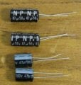
I grabbed two 47uF nonpolarised electros, and two 47uF polarised. (image 1)

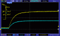
Image 2 shows the pair of 47uF NP caps being charged through a 47k resistor to approx 50v DC. The charge rate is 0.5C as you would expect for two caps in series.

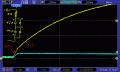
Image 3 shows two polarised 47uF caps, with diodes to make the reverse dioding effect occur at -0.7v, to make it more clear. The charge voltage is 10v. You can clearly see the caps charging quickly at 0.5C until the reversed cap "zeners", then all remaining charge occurs in the remaining cap at 1C.

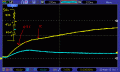
Image 4 is the two reversed polarised 47uF caps. It charges at 0.5C until the reversed cap zeners at about -10v (after that point the reversed cap zeners slightly lower at about -8v) but you can still clearly see a fast charge at 0.5C then it slows to 1C charge for the remainder of charge when the only cap charging is the non-reversed cap.

So if the electros are acting as non-polarised caps due to insufficient voltage condition it matches two non-polarised caps and Ct = 0.5C.

But if the reversed electro pair is doing it's job and exhibiting the behaviour of a polarised reversed electro pair, the correct formula is Ct = C.
 

Attachments

Last edited:
This test, while giving accurate results for what you've done, isn't relevant to a typical situation in which a pair of series electrolytics would be used.

You have applied a voltage of a single polarity to the series combination. If that were the circuit application, why would anyone bother to use two electrolytics in series? The reason for using this circuit is for circumstances where an AC voltage is going to be applied to the "synthetic" non-polar electrolytic.

Apply a +V to -V volt square wave (with a V of several volts at least) to your R-C-C network (the one with the diodes) and have a look at the waveforms across each cap, examining the time constant.

Assuming that the square wave generator ground can be isolated from the scope ground, you can connect the ground clips of two probes to the junction between the two caps, connect the probe tips to the other terminals of the caps, invert one channel of the scope and get a display of the voltage across each cap.
 
Last edited:

THE_RB

Joined Feb 11, 2008
5,438
Sure, I didn't bother testing the discharge condition. If I read you right you are saying the cap will show a different capacity using a different test?

I have a problem with saying that you can't measure the capacity of a cap by charging it from empty to X volts through a resistor. That is most definitely a real world capacitor situation.

And/or you are saying the capacitance is C under some operating conditions, and 0.5C under other operating conditions? If that is true, then is that really proof that the "capacitance" is 0.5C?
 
Sure, I didn't bother testing the discharge condition. If I read you right you are saying the cap will show a different capacity using a different test?
Why don't you try the experiment I suggested? You already have the scope and resistor/caps/diodes hooked up.

I have a problem with saying that you can't measure the capacity of a cap by charging it from empty to X volts through a resistor. That is most definitely a real world capacitor situation.
That not quite what I said. I didn't suggest that you can't measure the capacitance of a (single) "cap" that way; I was talking about the series connection of two electrolytic caps (with diodes to make the reverse clamping action precise).

While it's true that capacitors are used in that way, why would anyone use a series connection of two electrolytics if charging in one direction only would be the application? The reason for using two electrolytics in series is because the application will be applying AC.

And/or you are saying the capacitance is C under some operating conditions, and 0.5C under other operating conditions? If that is true, then is that really proof that the "capacitance" is 0.5C?
Added edit: I'm not saying that if two caps are in series, the capacitance of the combination isn't C when one of the caps is shorted, which is what you have after the opposing diode is turned on; it is C under that condition, but that's not the way such a series connection is usually used.

I'm saying that the effective capacitance of two electrolytics in series (with diodes), with AC applied, (not just doing a single charge operation, one time, in one direction only) is 0.5C.
 
Last edited:
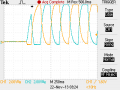
Here's what I get from a real circuit.

I used two 47μF caps, with their minus terminals connected together, and diodes across each cap. I used a 2200 ohm resistor in series with the two, and applied a +10V to -10V square wave. With both caps initially discharged, suddenly applying the square wave gave this result:


You can see one cap beginning to charge (blue trace) and the other trying to go negative, but the diode doesn't allow it to go more than a diode drop negative. The diode is conducting the same current as is conducted by the cap which is charging.


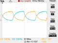
After a while we have the steady state situation shown in the next capture, where both caps make excursions in the positive direction, and almost go negative, but the diodes are no longer conducting much, if any, to keep a cap from going negative.

It's the fact that the diodes are no longer acting as shorts (because they're hardly conducting at all) that prevents the effect you show in your experiment, where you get an effective capacitance of C:


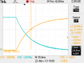
Here I've expanded the sweep and added a couple of cursors to measure the time constant (it's hard to get the cursors exactly right). The time measured is the time for the voltage across a cap to reach 63% of the maximum voltage.

If the effective capacitance were 47μF, I would expect a time constant of R*C = 2200*47*10^-6 = 103.4 mS. The measured time is 58 mS, about half what we would expect if the effective capacitance were in fact 47μF. Apparently, the effective capacitance is .5C:


Attachments

THE_RB

Joined Feb 11, 2008
5,438
Thank you very much for taking the time to do those tests. :) I did a few checks last night in the workshop and got similar results to yours.

I agree the effective capacitance of the pair after conducting AC for a while is definitely 0.5C.

So I apologise to everyone for saying earlier "the capacitance is properly 1C" as that is not proper at all. :)

I still have issues with the global statement that the capacitance is 0.5C though. The diodeing effect means the pair behaves unlike a proper unpolarised cap, it has a non-linearity to its charge discharge behaviour etc and it's capacitance depends on what the cap is actually doing at the time.

I think the best evaluation would be that a reversed polarised cap pair behaves like this;
1. operation under the diodeing voltage the capacitance is always 0.5C.
2. operation with a constant AC voltage or current means it behaves at 0.5C.
3. initial or special charge/discharge over diodeing voltage and over previous voltages it behaves at 1C.

Re the original post about making a non-polarised cap (and back to the other thread about Rif@@'s audio amp and my amp) a non-polarised electro is not needed unless the AC voltage that will appear across the cap is greater than +/- 5v (ie 10v p/p). Which in the vast majority of cases should be fine as the voltage on AC signal coupling caps is usually far less than that.
 
Re the original post about making a non-polarised cap (and back to the other thread about Rif@@'s audio amp and my amp) a non-polarised electro is not needed unless the AC voltage that will appear across the cap is greater than +/- 5v (ie 10v p/p). Which in the vast majority of cases should be fine as the voltage on AC signal coupling caps is usually far less than that.
You saw "reverse zenering" occurring at 8 to 10 volts. Capacitor manufacturers recommend not applying a reverse voltage anywhere near that great. For example, Cornell-Dubilier recommends not more than 1.5 volts (page 9 under the heading "Reverse voltage"):

http://www.cde.com/catalogs/AEappGUIDE.pdf

I've seen other manufacturers recommend not more than 1 volt, which is the number I've always gone by. Even a limit as low as 1 volt allows the .7 volt silicon diode drop as permissible.

I still have issues with the global statement that the capacitance is 0.5C though. The diodeing effect means the pair behaves unlike a proper unpolarised cap, it has a non-linearity to its charge discharge behaviour etc and it's capacitance depends on what the cap is actually doing at the time.
If the "diodeing effect" is not due to the caps themselves, but is due to actual silicon diodes, there won't be any significant non-linearity in steady state AC operation. Notice in the scope capture that the voltage across the caps in AC operation doesn't even go negative by a full diode drop. A silicon diode conducts some when the applied voltage is below .7 volts (remember the exponential characteristic; it's not a sudden hard turn on), and that's why the steady state reverse voltage experienced by the caps is below .7 volts.

I think the best evaluation would be that a reversed polarised cap pair behaves like this;
1. operation under the diodeing voltage the capacitance is always 0.5C.
2. operation with a constant AC voltage or current means it behaves at 0.5C.
3. initial or special charge/discharge over diodeing voltage and over previous voltages it behaves at 1C.
With respect to condition 1, electrolytic capacitors should never be operated with sufficient reverse voltage to cause the cap itself to "diode". Actual silicon diodes should be employed.

With respect to condition 3, if the pair has been operating for a while, and the applied AC voltage suddenly goes higher than it had been, the 1C operation only lasts for a couple of cycles or so.

I wonder what an actual non-polarized electrolytic does at initial application of a voltage. I'll dig one out and make some measurements.
 
This reminds me of a recent thread where a nonpolarised cap was specced to be used in the feedback circuit of an audio amp chip. We were discussing whether that AC waveform needs a nonpolarised cap or if a standard polarised electro would do. Seeing that that signal is <=1v p/p it looks like any polarised electro should be fine?
This raises an interesting question. What will happen to an electrolytic capacitor if it is exposed to a reverse voltage of 1 volt (or maybe a little less) for a long time (how long)? Will it reform and change its value? I think I'll try this. I'll measure an electrolytic's capacitance and then apply a reverse 1 volt for a week or so and see what happens. Also, how about exposing it to a 2 volt P/P (+1 volt to -1 volt; that would apply 1 volt in the reverse direction) for a while?
 

THE_RB

Joined Feb 11, 2008
5,438
You saw "reverse zenering" occurring at 8 to 10 volts. Capacitor manufacturers recommend not applying a reverse voltage anywhere near that great. For example, Cornell-Dubilier recommends not more than 1.5 volts (page 9 under the heading "Reverse voltage"):

http://www.cde.com/catalogs/AEappGUIDE.pdf

I've seen other manufacturers recommend not more than 1 volt, which is the number I've always gone by. Even a limit as low as 1 volt allows the .7 volt silicon diode drop as permissible.
Thanks for th einfo. Re the measured reverse zener voltage it was as low as 5v on some electros, but yeah 5-8v would be typical based on the handful of uF values and voltage ratings that I tested.


If the "diodeing effect" is not due to the caps themselves, but is due to actual silicon diodes, there won't be any significant non-linearity in steady state AC operation. Notice in the scope capture that the voltage across the caps in AC operation doesn't even go negative by a full diode drop.
Understood and agreed. In steady state symmetrical AC operation the caps hardly go negative at all, after X cycles they "balance" out with each cap going the least negative that it can.


With respect to condition 1, electrolytic capacitors should never be operated with sufficient reverse voltage to cause the cap itself to "diode". Actual silicon diodes should be employed.
Interesting! So this means you CAN'T make a non-polarised cap from two reversed electros, you need two reversed electros and two diodes? That goes against what I was taught and have seen in numerous instances.

With respect to condition 3, if the pair has been operating for a while, and the applied AC voltage suddenly goes higher than it had been, the 1C operation only lasts for a couple of cycles or so.
Agreed, but even if it is occasional behaviour it is still a valid part of the operation of a dual reversed electro pair, and that's why I don't like the blanket statement "capacitance is 0.5C" as that only applies to part of the operation.

I wonder what an actual non-polarized electrolytic does at initial application of a voltage. I'll dig one out and make some measurements.
From what I understand a NP electro is much larger for the same uF because it has two internal plate windings, reversed, so it is internally exactly like a reversed series electro pair.

If so, that raises the question re your earlier point that it's not safe without the diodes. There may be two reversed plate windings inside an NP cap but there is very unlikely to be any diodes... ;)
 
Interesting! So this means you CAN'T make a non-polarised cap from two reversed electros, you need two reversed electros and two diodes? That goes against what I was taught and have seen in numerous instances.
If one observes the restrictions found in the manufacturer's application data, then diodes are necessary. But, what happens when diodes are left out? I think the reverse voltage (after application of AC) doesn't stay at the "reverse zener" voltage. I think it is much less. You could check this, and when I get back to the lab, I'll check it too with a number of caps.

From what I understand a NP electro is much larger for the same uF because it has two internal plate windings, reversed, so it is internally exactly like a reversed series electro pair.
It seems reasonable to expect it to be about twice as large (in volume).

If so, that raises the question re your earlier point that it's not safe without the diodes. There may be two reversed plate windings inside an NP cap but there is very unlikely to be any diodes... ;)
Yes, this is an interesting point, and I don't know the answer. Perhaps since both windings are in a single can, exposed to only one electrolyte, some effect prevents a problem. An application engineer at a manufacturer may be able to answer the question.

But, with two separate caps, complying with the manufacturer's recommendation to apply no more than 1.5 volts reverse would seem to require the use of diodes. :confused:
 

THE_RB

Joined Feb 11, 2008
5,438
I think the safety aspect would depend on the current involved.

As you said, the reverse zener voltage drops a bit over time, but from what I saw with low currents it peaked at 8-10v and reduced in mS to 5-8v or so, then remained there for minutes.

But the lowest value resistor I used was 1k, on 10v supply so with the cap at -5v that would have been 5mA reverse current (so -5v * 5mA = 25mW).

I'm not sure if sustained reverse operation at 25mW is enough to damage the electrolyte?

Also, in AC pair use the cap would only be subjected to -ve operation for half of the cycle and at low current, the bulk of the charge/discharge voltage and current of each cap occurs in the positive direction. Maybe that is enough to rejuvenate any small damage to the electrolyte etc caused in the -ve direction?
 

Wendy

Joined Mar 24, 2008
23,869
Interesting discussion. The only reason I can think of to use a non-polarized electrolytic cap is generally audio, specifically the low frequency audio component.

What other applications do you see for something like this?
 

THE_RB

Joined Feb 11, 2008
5,438
For times when you need a high capacitance, on AC or which may be exposed to reversed voltage.

Situations like speaker crossover networks have high value NP electro caps and high intermittant peaks currents etc, the 0.5C/1C behaviour might be an issue there.

I do get your point that the most common use would be AC signal coupling.
 
Last edited:

MrChips

Joined Oct 2, 2009
35,296
Two places I have encountered non-polar capacitors:

1) in speaker cross-overs,

2) in the original Apple Macintosh horizontal fly-back circuitry.
 
Thread starter Similar threads Forum Replies Date
oh_uh_okay General Electronics Chat 2
Top