plotter cutter power circuit help

Thread Starter

trevo

Joined Apr 27, 2017
9
Hi I'm a newbie here, looking for some circuit help
I have a redsail 1360c plotter cutter or sticker cutter that is playing up- it can cut intricate patterns in paper or vinyl and takes paper 1360mm wide and is run by computer software.
when I turn it on with the switch the lcd screen flashes on, the plotter knife goes down and then it stops (screen off, knife up) and it does it again every second flash/ up/ down. it's supposed to travel to the right and be ready to cut with the lcd on. I bought it like this and the seller said it worked once from new and then did this , although it looks like it's done more work than one!

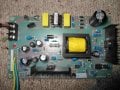
I looked inside and the power supply circuit has 240v going in, the fuse is good and it has 3 connectors coming out - one ground - one 28v and lastly -8v but the -8v reads about -0.5 and the 28v has about 3v coming out.
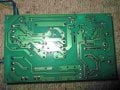
The board looks clean and nothing looks or smells burnt out or defective

I've had some help on another forum that has stopped but this is where we got to..
The 240v input goes up to a mosfet svf4n60f (far right) this looks to feed the transformer in the middle with around 300vdc to the sides and ocillating between 150 and 400vdc to the middle. Nothing seems to come out of the transformer, but it does have contenuity a quick test of the diodes inc the big one and the mbrf 10200ct (middle bottom) seems OK
I think the octocoupler is OK but unsure
I think it should be a simple fix but I'm out of my depth!
cheers trev
 

Attachments

AlbertHall

Joined Jun 4, 2014
12,346
It is a switch mode power supply. They are very rarely easy to fix even with the schematic and experience repairing the things.
Without a schematic it is nigh impossible.
(Quite a few years spent repairing them, and then teaching others how to repair them)
 

Thread Starter

trevo

Joined Apr 27, 2017
9
Hi Albert, thanks for the input-- if worst came to worst, could I just take each component out and test it- say from the transformer onwards? can you say why it's impossible to trace?
cheers trev
 

AlbertHall

Joined Jun 4, 2014
12,346
When they fail it is usually a cascade. That is, one component fails which stresses another component which then fails and so on. If you don't find all the faulty components then it will probably go bang again. Without a schematic, when you find a faulty component, you can't know which components may have been stressed by that failure. The voltages involved are quite high and you can't test the capacitors and semiconductors at voltage without some fancy equipment.

Usually when faultfinding you apply power and then make some measurements to discover where the problem is. You generally can't do that as described above but also it would require great care to do that as all the primary circuit is live mains
 

Dodgydave

Joined Jun 22, 2012
11,302
There is an 8 pin chip on the pcb, that will be the switchmode chopper, the 4 pin chip is an opto-coupler this is used to monitor the output voltage with a TL431, for the chopper chip, i think the chip is going into overcurrent shutdown because of the blown mosfet,or faulty output rectifier,
unless you're familiar with switchmode psus, you won't have much luck in repairing it.

The chip could be a UC3845 series..

Can you see the markings on the 8 pin chip?
 
Last edited:

Thread Starter

trevo

Joined Apr 27, 2017
9
TL431,
-- the blown mosfet,or faulty output rectifier--
The chip could be a UC3845 series..

Can you see the markings on the 8 pin chip?
yes TL431AA for the trans looking thing
-do the figures of 300 sides and up and down middle pin of 150 to 350v suggest a blown mosfet? and by rectifier are you looking at the 4 diodes at the top (which seem to read OK) or that double diode thing with heatsink (which also tested OK) or which bit is the output rectifier ?
the 8 pin chip has KA3842A on it.
I'm hoping something obvious can be done but if not is there common 28v and -8v switch power supplies available?
cheers trev
 

Thread Starter

trevo

Joined Apr 27, 2017
9
at worst could I just replace all that can't be tested to read OK - caps etc, there only seems to be around 50 components to unsolder to check beyond the initial (top) bit going across to the mosfet.. ?
 

Dodgydave

Joined Jun 22, 2012
11,302
yes TL431AA for the trans looking thing
-do the figures of 300 sides and up and down middle pin of 150 to 350v suggest a blown mosfet? and by rectifier are you looking at the 4 diodes at the top (which seem to read OK) or that double diode thing with heatsink (which also tested OK) or which bit is the output rectifier ?
the 8 pin chip has KA3842A on it.
I'm hoping something obvious can be done but if not is there common 28v and -8v switch power supplies available?
cheers trev
Then its a UC3842 chip and a TL431 zener regulator.

There is a circuit using this method on datasheet..pg21, you can follow it and redraw it with your component values.

http://www.ti.com/product/UC3842

Start by checking the mosfet for shorts, ( remove from circuit for testing)and the twin diode on the heatsink at the side is for +28V, The large single diode is for -8V, there are two capacitors per out, and two inductors.
 
Last edited:

Thread Starter

trevo

Joined Apr 27, 2017
9
Then its a UC3842 chip and a TL431 zener regulator.

There is a circuit using this method on datasheet..pg21, you can follow it and redraw it with your component values.

http://www.ti.com/product/UC3842

Start by checking the mosfet for shorts, ( remove from circuit for testing)and the twin diode on the heatsink at the side is for +28V, The large single diode is for -8V, there are two capacitors per out, and two inductors.
Great, thanks for the starting point-- one thing though, I have checked both of those output diodes out of circuit already and they're good- I haven't had the mosfet off yet- will do today
since both the 28 and -8v are both down, does this indicate the problem being further up circuit?
can the tl431 affect both outputs?
cheers
 

Dodgydave

Joined Jun 22, 2012
11,302
The tl431 will monitor the 28V, if this is low or faulty, both outputs will be low at the same time. All switchmode psus work on the same principle they only monitor one output, usually the main supply, all outputs will track up or down at the same time. I don't think it will be the tl431 or the opto-coupler, my bet is the mosfet.
 

Thread Starter

trevo

Joined Apr 27, 2017
9
OK I have the mosfet out it's a svf4n60f n-type and I think maybe duff as the resistance between the drain and source is 26k one way and no continuity the other.. (read online that that's bad)
thanks dave - is there another check for what may have made it go bad or what it could've made go bad before I put another one in?
cheers again
 

Dodgydave

Joined Jun 22, 2012
11,302
Mosfet sounds ok, so it will be the output side pulling it down, or the chip is in soft start mode. Time for hair pulling.....
 
Top