PLL Design Requirement

Thread Starter

Nomi 1114

Joined Dec 4, 2017
124
Dear all,

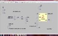
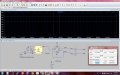
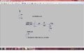
I hope everyone is fine. I would like to ask that we have already designed 7.7MHz - 8.7MHz VCO, now i am interested to design a (Phase looked loop) PLL for same frequency band. i designed one circuit which is attached below but results are not good.. i am not sure why it is not working well, weather i didn't set the exactly parameters or something else !! need help from experts, i can also share both schematic of PLL and VCO if needed. Normally 74HC4046 or CD4046 used for the said purpose but unfortunately i am unable to implement/simulate this model into LTspice. i shall be highly grateful to him/her if somebody is ready to help me.

Anxiously waiting for prompt response and thanks in advance.

Regards
Numan
 

Attachments

crutschow

Joined Mar 14, 2008
38,504
The CD4000 series digital circuits will only work to a few MHz, not 8MHz.

You schematic only shows one input to the gate, it needs two, so that's why "results are not good".
 

Thread Starter

Nomi 1114

Joined Dec 4, 2017
124
The CD4000 series digital circuits will only work to a few MHz, not 8MHz.

You schematic only shows one input to the gate, it needs two, so that's why "results are not good".
Dear crutschow,

First of all i would like to say thank you very much for your interest and cooperation. secondly i would like to tell you that i already applied the 2nd input to the XOR gate, but in the previous uploaded attachment i didn't mentioned. now for your information and further suggestions i am uploading whole schematic.

I would like to inform you that i have designed VCO ranging from 7.7MHz to 8.7MHz. the uploaded schematic in fig 1 consist on another VCO which is not required for me. so i wanna replace this VCO with our designed VCO, but i am bit confused about the connections. i think don't have sufficient knowledge or maybe beginner stage in this area. your help and suggestions will be highly appreciated.

It is my request please observe the circuit critically and suggest me how can it work in the right way, my aim is to design PLL with VCO containing frequency wide band from 7.7Mhz to 8.7MHz.

Regards
 

Attachments

DickCappels

Joined Aug 21, 2008
10,661
Just windering what the PLL will be used for. The '4046 is not suitable for some kinds of applications.

One version has an R/S flip/flop phase detector which may be best for your application.
 

ronsimpson

Joined Oct 7, 2019
4,691
7.7MHz - 8.7MHz VCO, ...…….. Normally 74HC4046 or CD4046 used for
I have used a 74hc4046 up to 18mhz with 5V supply. Not 3.3V. The CD4046 has a top end of 1 to 2mhz.

The 74hc4046 has a VCO that works very well. There are three types of frequency/phase comparators. Chose wisely.
 

Thread Starter

Nomi 1114

Joined Dec 4, 2017
124
Just windering what the PLL will be used for. The '4046 is not suitable for some kinds of applications.

One version has an R/S flip/flop phase detector which may be best for your application.
Dear DickCappels,

Exactly sir, HC4046 is good option but i am unable to implement in LTspice, i have downloaded 74hc .lib but still unable to find desired results. if you help me for implementation of 4046 in same software containing frequency band from 7.7MHz to 8.7MHz, then i shall be highly grateful to you for this act of kindness.

looking forward for your kind and positive response.

Regards
 

Thread Starter

Nomi 1114

Joined Dec 4, 2017
124
I have used a 74hc4046 up to 18mhz with 5V supply. Not 3.3V. The CD4046 has a top end of 1 to 2mhz.

The 74hc4046 has a VCO that works very well. There are three types of frequency/phase comparators. Chose wisely.
Dear Respected ronsimpson,

First of all Thank you very much for your kind help and positive response again and again. As you helped me previously for designing of VCO as i desired, Now if you help me again for implementation of 4046 in same software containing frequency band from 7.7MHz to 8.7MHz, then i shall be highly grateful to you for this act of kindness. You can use 5V no problem, input voltages are not specifically bounded but out frequency and voltages are considerable, but at input frequency signal type will triangular waveform holding frequency 180Hz as you used in previous cct of VCO.

looking forward for your kind and positive response.

Regards
 

Thread Starter

Nomi 1114

Joined Dec 4, 2017
124
I have used a 74hc4046 up to 18mhz with 5V supply. Not 3.3V. The CD4046 has a top end of 1 to 2mhz.

The 74hc4046 has a VCO that works very well. There are three types of frequency/phase comparators. Chose wisely.
Dear Sir,


Can you send me the library of 74HC4046 with .asy file, i shall be highly grateful to you for this act of kindness ...


Retgards
 

Thread Starter

Nomi 1114

Joined Dec 4, 2017
124
hello every one,

hope you all are fine. here i would like to ask one question. I have Designed VCO frequency ranging from 7.7MHz ~ 8.7MHz, it works well. I wanna use inverted (complemented ) signals at a same time. for this purpose i used 74HC74 (Dual D-type flip-flop with set and reset; positive edge-trigger ) and further 74HC00 (Quad 2-input NAND gate ) as mentioned in attached images. But i am facing one problem the output frequency of 74HC74 is half of input frequency means at 7.7MHz i have 3.8 MHz (divided by 2). Please suggest me how can i get the same frequency at output of 74hc74 means 7.7MHz = 7.7MHz, 8MHz = 8MHz, 8.7MHz = 8.7MHz

Looking forward for your kind and prompt response.

Regards
 

Attachments

danadak

Joined Mar 10, 2018
4,057
Place a X2 in the output path, basic method

1579872852161.png


https://vlsiuniverse.blogspot.com/2016/07/clock-multiply-by-two.html

Delay element typically RC low pass filter/delay network. Or series gate delays
another way.

Your D then will regenerate 50% duty cycle.

Note its preferred to use PLL at double freq vs do it above method.
Because delay this way is sloppy in tolerance board to board, part to
part. But for one off, T and V relatively stable OK.

You can use single gate logic for the XOR - http://www.ti.com/lit/scyt129


Regards, Dana.
 
Last edited:

Thread Starter

Nomi 1114

Joined Dec 4, 2017
124
Delay element typically RC low pass filter/delay network. Or series gate delays
another way.
Dear Respected danadak,

Hope you are fine and enjoying your time. as per your suggestions i made changes in the circuit, but unfortunately failed to get results as desired, after placing XOR my output goes to DC level. i am uploading my 2 schematic files, please review critically and suggest me how can i get at OUT4 and at OUT5 complementary signals containing frequency 7.7MHz to 8.7MHz with FM as avail at the output of LTC1799 (OUT).

Anxiously waiting for your positive and prompt response.

With kind Regards
Nomi
 

Attachments

Thread Starter

Nomi 1114

Joined Dec 4, 2017
124
Dear Respected @ronsimpson, @DickCappels and @crutschow,

I need your help and kind suggestion too. i also know that you are very busy have having tight schedule, sorry for disturbance. but i wanna finish this work as early as possible. As i told you before that i am new in this area so that's why i am facing problems and need your help please.


looking forward for your kind and positive response please .

With kind Regards
Nomi
 

danadak

Joined Mar 10, 2018
4,057
One gate delay not enough in XOR path, here is an example -

1580039148625.png


You can adjust RC network to get better results.


Regards, Dana.
 

Thread Starter

Nomi 1114

Joined Dec 4, 2017
124
Here is a little better look (note run at 10 Mhz) ....

View attachment 197625


Regards, Dana.
Dear Dana,

Thank you very much for your effort. i did experiment as suggested. for XOR gate i used CD4070 an cd4030 ICs. but at out i found DC level, i am not sure why is it. here most important point is at input of XOR gate signal's frequency is 7.7MHZ to 8.7 MHz and Time period of signal is 129.8ns ~ 114ns... might be this is the reason. so please suggest me an IC which can work at the said frequency and time period.

For your reference Schematic is attached ... have a look on images and schematic and reply me please .

looking forward for your kind reply


Regards
 

Attachments

Thread Starter

Nomi 1114

Joined Dec 4, 2017
124
Hello,

You might want to look at the CD74HC4046 or CD74HCT4046.
Those will work upto 18 Mhz.

Bertus
Dear bertus,

thanks for your reply and concern. i already mentioned in above post actually i need SPICE model for 74HC4046, i found .asy file but didn't found SPICE medel, .lib file, .sub file. so if you have please send me. I shall be highly grateful to you for this act of kindness..

waiting for your prompt reply..

Regards
 

danadak

Joined Mar 10, 2018
4,057
Dear Dana,

Thank you very much for your effort. i did experiment as suggested. for XOR gate i used CD4070 an cd4030 ICs. but at out i found DC level, i am not sure why is it. here most important point is at input of XOR gate signal's frequency is 7.7MHZ to 8.7 MHz and Time period of signal is 129.8ns ~ 114ns... might be this is the reason. so please suggest me an IC which can work at the said frequency and time period.

For your reference Schematic is attached ... have a look on images and schematic and reply me please .

looking forward for your kind reply


Regards
You need to use HC logic, 74HC86, CD4xxx logic is too slow for this application.


Regards, Dana.
 

Thread Starter

Nomi 1114

Joined Dec 4, 2017
124
You need to use HC logic, 74HC86, CD4xxx logic is too slow for this application.


Regards, Dana.
Thank you very much dear Dana, now it's looks better, i am working on it, if i feel any problem, i must contact you again ... but again thank you very much for your kind cooperation and kind help, such a nice and kind personality .....

Regards
Nomi
 
Top