 Facebook
 Google
 GitHub
 Linkedin
I have designed a arduino based project to automate my hen house. I designed and printed the PCB, populated it and wrote the code. Everything works except I screwed up the simplest part of the board.
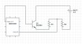
One of my sensors detects the voltage in the battery / solar panels. What I attempted (see attached) was for the arduino to send a signal to a transistor to turn on and allow the voltage in the battery to flow into a voltage divider where the ardunio would then read the voltage present there. The problem is the transistor's base is 5v and the collector is 6v so I am only getting around 4.3 volts from the emitter. Obviously I forgot about this simple fact before I made the PCB.
(Also it is not shown in the schematic but the arduino and battery share a ground.)
I know I can bypass the transistor and just connect 6v to R1 but I don't want to waste the power when I am not sensing anything.
What do you feel is the easiest way to fix this?
Attachments
-
 49.4 KB Views: 28

")


