Please explain this op-amp circuit with resistors, capacitors, and diodes

Thread Starter

BasicPoke

Joined Apr 30, 2013
11
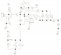
Hello, Could anyone please explain how this circuit works. I have looked at some standard op-amp circuits in a TI paper and this one is closest to a low noise differentiator. I find this in an audio amp circuit, amplifying an audio transducer. We are getting more noise at the output than we want, not sure the source. There is a sort of low pitch roaring and electronic switching noise. Any tips on what the gain of this circuit is and how to reduce it? FYI, I am an EE but not very versed on op amps.
Thanks
Ron
 

Attachments

#12

Joined Nov 30, 2010
18,224
The gain is almost 1100 v/v. The gain is -(R14+R43)/R26
Way too much gain and a noisy chip in the first place at 15 nv/root Hz.
The low frequency noise is coming from the 25nv/root Hz in the 1/f region.
The diodes on the output are causing sudden changes in gain.

Wrong chip. Too much gain.
C14+R26 limits the audio band to frequencies above 159 Hz.
Start over. This circuit sucks for noise performance and most audio applications.
 

Attachments

bertus

Joined Apr 5, 2008
22,276
Hello,

As #12 said the gain is about 1100 times, but until the output voltage is ± 0.7 Volts.
Above the ± 0.7 Volts the gain is reduced to 100.
This is a kind of " soft" clipping.

Bertus
 

bertus

Joined Apr 5, 2008
22,276
Hello,

The schematic is not on page 62 of the given PDF.
I have looked in some if TI' s PDF's, but opamps are shown in fat blue, and yours is shown in thin black.
You must have found it in an other PDF.

Bertus
 

Thread Starter

BasicPoke

Joined Apr 30, 2013
11
Hello,
The schematic is not on page 62 of the given PDF.
I have looked in some if TI' s PDF's, but opamps are shown in fat blue, and yours is shown in thin black.
You must have found it in an other PDF.
Bertus
The schematic that I originally posted was generated by my company and we have implemented the circuit and observed the problems as I described. The TI paper shows a differentiator circuit that looks very much like my circuit, with a cap and resistor on the input, and a cap and resistor in the feedback.
Ron
 

bertus

Joined Apr 5, 2008
22,276
Hello,

So the circuit is derived from this circuit of the PDF:

Low_noise_differentiator.png

And added a soft clip feature into the circuit.

Bertus
 

Thread Starter

BasicPoke

Joined Apr 30, 2013
11
Hello,
So the circuit is derived from this circuit of the PDF:
View attachment 106717
And added a soft clip feature into the circuit.
Bertus
If that was a question, no the circuit was not derived from that PDF. I have no idea how the circuit was derived since I cannot talk to the person who designed it. We are using it because it worked in a similar application. Whether that was a good decision or not, I don't know. I found the PDF when I was trying to figure out how the circuit worked.

Maybe that was not a question. If not, my apologies.
Ron
 

kubeek

Joined Sep 20, 2005
5,795
If that was a question, no the circuit was not derived from that PDF. I have no idea how the circuit was derived since I cannot talk to the person who designed it. We are using it because it worked in a similar application. Whether that was a good decision or not, I don't know. I found the PDF when I was trying to figure out how the circuit worked.

Maybe that was not a question. If not, my apologies.
Ron
the circuit is basically a high-pass filter with a lot of amplification and soft clipping aroung some input level. What you probably should be talking about is what problem are you trying to solve, not why this copied circuit sort of does work but not good enough.
As always, solving your problem is much easier than mending your solution.
 

nomurphy

Joined Aug 8, 2005
567
The source of the noise is the amount of gain. Are you sure the circuit is copied correctly?
A single stage of Av > 1,000 is going to be noisy and beyond the capacity of the op amp.
Also, note the pin-1 output is going to have a DC bias of AVCC / 2.
What is the functional intent of using this circuit as shown?
 

seanstevens

Joined Sep 22, 2009
253
Noisy and soft clipping, together with the two back to back diodes on the output of the opamp is almost the configuration used on guitar sound effect units used to be called Fuzz Box.
 

Thread Starter

BasicPoke

Joined Apr 30, 2013
11
the circuit is basically a high-pass filter with a lot of amplification and soft clipping aroung some input level. What you probably should be talking about is what problem are you trying to solve, not why this copied circuit sort of does work but not good enough.
As always, solving your problem is much easier than mending your solution.
What I need is quiet amplification of the audio from a transducer. I can't tell you what gain I need, will have to do some experimentation. There is another stage of amp after this, so I'm sure a much lower gain would work. I'm thinking of trying about 100. I don't see any reason for soft clipping. If it clips in response to a large input, that's fine. I would like to stick with this amp and general configuration. It works adequately, and is very quiet, on another product of ours. I read that metal film (thin film) resistors are quieter. Do you think it would be worth a try replacing the thick film resistors I am using?
Thanks
Ron
 

AnalogKid

Joined Aug 1, 2013
11,037
OK, we can work with that.
What are the bandwidth limits of the incoming signal?
Do you want this preamp to include any highpass or lowpass filtering?
What is the input signal voltage range?

ak
 

Thread Starter

BasicPoke

Joined Apr 30, 2013
11
I want to stick with essentially the same circuit. I might consider a drop-in replacement amp with lower noise, if that exists.

Do you think I could get a significant reduction in noise from my circuit (see original post) by replacing the standard resistors (I believe carbon film) with metal film, and replacing the ceramic capacitors with film capacitors?
Ron
 

crutschow

Joined Mar 14, 2008
34,411
Is the basically white noise you are seeing (hiss).
Metal film resistors may help a little but different capacitors are unlikely to have any effect.
A lower noise op amp may also help.
The one you are using has noise of 15nV/√Hz.
Look for one below a few nV/√Hz such as the LT1115 or LT1028.
 

AnalogKid

Joined Aug 1, 2013
11,037
In the original schematic, R28 and R42 form a 0.1 dB attenuator (not much). R6 and R30 form a 10.5 dB attenuator, definitely something to question. If you can eliminate this attenuator and reduce the opamp gain by 10 dB, noise performance will improve.

ak
 

crutschow

Joined Mar 14, 2008
34,411
In the original schematic, R28 and R42 form a 0.1 dB attenuator (not much). R6 and R30 form a 10.5 dB attenuator, definitely something to question. If you can eliminate this attenuator and reduce the opamp gain by 10 dB, noise performance will improve.
It may improve slightly, but not by much, since it's the op amp noise and its gain that determines the signal to noise ratio.
Thus reducing the op gain by 10.5dB and eliminating the output attenuator loss of 10.5dB will have little effect on the S/N of the signal.
 

Thread Starter

BasicPoke

Joined Apr 30, 2013
11
In the original schematic, R28 and R42 form a 0.1 dB attenuator (not much). R6 and R30 form a 10.5 dB attenuator, definitely something to question. If you can eliminate this attenuator and reduce the opamp gain by 10 dB, noise performance will improve.

ak
We were thinking the same thing. You don't want to divide the signal just to amplify it later (there is a Bluetooth module downstream that has an internal amp). But I tried different dividers there (R8 and R30) and no divider (removing R30) then adjusted the Bluetooth module gain to get the same volume level using a known input sound, and the noise level was very similar. So it appears changing this divider does not help.

I have also tried changing the gain of this amp circuit to 200 and adjusting the downstream Bluetooth module gain to compensate. Didn't help with noise there either.
Ron
 
Top