Please check Schematic for 555 timer one shot of 100ms

Thread Starter

riddhi_shah

Joined Apr 3, 2017
8
Hello Pundits,

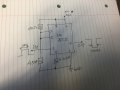
I am using 555 Timer for my application, in my application tester have to send the end of test (EOT) signal to the ATE machine when start of test is recieved from machine of 2ms. Can anyone help me with the schematic. I am attaching an ideal schematic with RC calucated, if anyone can provide feedback on same that would be much appreciated.

Also, currently I don't have any simulator to test this schematic, so help would be great.

Thanks.
 

Attachments

128ITSH

Joined Jul 20, 2017
101
What is exactly the purpose of this circuit:
What pulse width is coming in, what delay should be before a pulse is sent out, and what width is that pulse too?
 

Thread Starter

riddhi_shah

Joined Apr 3, 2017
8
I am making a small pcb board which is a interface between gravity handler and tester from client end, now once the handler triggers the active high signal of pulse width 8ms which is received and becomes input of 555 timer (pin 2) and should send out signal active low of pulse width 100ms, upon sending(triggering) this signal handler stops its operation. Hope this helps to clear the idea.

Thanks.
 

Audioguru

Joined Dec 20, 2007
11,248
Please read the datasheet for the LM555:
1) Its trigger input at pin 2 is a negative pulse, not a positive pulse.
2) The output at pin 3 is a positive pulse, not a negative pulse.

Your 45uF capacitor is probably electrolytic with a wide range of tolerance producing poor accuracy. If the 2k resistor is changed to 2M then a 45nF film capacitor can be used that has very narrow tolerance. 45 is not a standard value so a 33nF can be parallel with a 12nF.
 

dl324

Joined Mar 30, 2015
16,846
my application tester have to send the end of test (EOT) signal to the ATE machine when start of test is recieved from machine of 2ms. Can anyone help me with the schematic. I am attaching an ideal schematic with RC calucated, if anyone can provide feedback on same that would be much appreciated.
What you want to do might be clearer if you provided a timing diagram and explained how the circuit is, or isn't, doing what you want it to do.

For starters, direct coupling your trigger signal is going to cause problems.
 

crutschow

Joined Mar 14, 2008
34,285
You need to add an inverter, either transistor or digital, to both the 555 input and output to get the signal polarities you want.
 

Thread Starter

riddhi_shah

Joined Apr 3, 2017
8
Please read the datasheet for the LM555:
1) Its trigger input at pin 2 is a negative pulse, not a positive pulse.
2) The output at pin 3 is a positive pulse, not a negative pulse.

Your 45uF capacitor is probably electrolytic with a wide range of tolerance producing poor accuracy. If the 2k resistor is changed to 2M then a 45nF film capacitor can be used that has very narrow tolerance. 45 is not a standard value so a 33nF can be parallel with a 12nF.
This is what I came up from Multisim simulation, using the R and values as said gave me result of 2ms instead of 100ms which is triggering waveform. Please see attached screen shot. Thanks.
 

Attachments

Audioguru

Joined Dec 20, 2007
11,248
You and Multisim do not know how to connect the 12nF and 33nF capacitors in parallel to make 45nF.
The output will be 1.1 x 2M x 45nF= 99ms. You have 1.1 x 2M x 12nF= 26.4ms.
Your 'scope is connected to the input of the 555, not to the output of the 555.
What is nfF?? Nano Farads is nF.
 

Thread Starter

riddhi_shah

Joined Apr 3, 2017
8
You and Multisim do not know how to connect the 12nF and 33nF capacitors in parallel to make 45nF.
The output will be 1.1 x 2M x 45nF= 99ms. You have 1.1 x 2M x 12nF= 26.4ms.
Your 'scope is connected to the input of the 555, not to the output of the 555.
What is nfF?? Nano Farads is nF.
Oops, Multisim knows it:) but my bad attached it wrong screenshoot.
 

128ITSH

Joined Jul 20, 2017
101
Looks like that worked, I get almost or kind off 100ms trail of cycle:D but I still want to make it just as one shot not more than one waveform, what would you suggest?
What do you mean by this?
Do you mean it can be activated only once in a power cycle, which means you have to take power off then on to reactivate?
Your circuit is a one-shot configuration of the 555... what makes it non-one-shot?
Please explain what exactly do you want it to do.
 

crutschow

Joined Mar 14, 2008
34,285
Below is the 555 configured to give one output pulse per input pulse, independent of how long the input pulse stays low or high.
Note that it triggers on the input pulse negative edge and the output pulse is positive going.

upload_2018-5-10_13-28-53.png
 
Top