Facebook
 Google
 GitHub
 Linkedin

Hi all
I am currently working on a 3D printer project http://www.reprap.org which I am finding every interesting. It is exposing me to a great deal of disciplines I have never worked with. One being electronics.
I am currently trying to design a stripboard mount for a pololu stepper driver and although I have found a number of solutions none are quite what I want.
Anyway - to my specific issue. The board provides 3 pins which are used to tell the chip the level of microstepping required. All the way from full stepping down to 1/18'th of a step.
The MS2 and MS3 pins have internal pulldown resistors and I will be adding a pulldown resistor to MS1 to ensure it does not float when I wish to do full stepping.
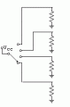
I am connecting DIP switches to these 3 pins so I can manually set the microstepping level by pulling the pins high.
I am confused though, since I imagine the 5v side would have a resistor to prevent too much current flowing through the pins in the event of a fault condition. If I place a resistor on the 5v side and throw the dip switch we have the pin connected to GND via the pulldown resistor and to 5v with another resistor. I cannot understand what the pin will actually be at. High or Low? I want it to go high if I throw the DIP switch.
Hope you guys understand my question and can point me in the right direction.
thanks
I am currently working on a 3D printer project http://www.reprap.org which I am finding every interesting. It is exposing me to a great deal of disciplines I have never worked with. One being electronics.
I am currently trying to design a stripboard mount for a pololu stepper driver and although I have found a number of solutions none are quite what I want.
Anyway - to my specific issue. The board provides 3 pins which are used to tell the chip the level of microstepping required. All the way from full stepping down to 1/18'th of a step.
The MS2 and MS3 pins have internal pulldown resistors and I will be adding a pulldown resistor to MS1 to ensure it does not float when I wish to do full stepping.
I am connecting DIP switches to these 3 pins so I can manually set the microstepping level by pulling the pins high.
I am confused though, since I imagine the 5v side would have a resistor to prevent too much current flowing through the pins in the event of a fault condition. If I place a resistor on the 5v side and throw the dip switch we have the pin connected to GND via the pulldown resistor and to 5v with another resistor. I cannot understand what the pin will actually be at. High or Low? I want it to go high if I throw the DIP switch.
Hope you guys understand my question and can point me in the right direction.
thanks