PLC Programming - Need help

Thread Starter

KKona

Joined Dec 3, 2018
6
Hi!

I have a single task, that I need to complete in the software Codesys. I'm at a completely beginner stage, since I have industrial background.
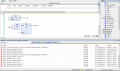
Maybe someone could help me out? I have done some programming of the task, but I think it is wrong and im confused as well. I have programmed it in Function Block Diagram since im better known with that than ladder.

The task is as following:
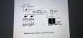
a two color mixer must be controlled with PLS. The device works like this:

- When start switch S0 is operated, lamp H0 (refill) lights up. valve Y1 opens and pump M2 starts

- When sensor S1 is covered with liquid, valve Y1 closes and valve Y2 is opened.

- When sensor S2 is covered with liquid, close valve Y2, pump M2 and lamp H0 turn off and M1 starts

- After 6 seconds, M1 stops

- The unit can be switched off at any time with switch S6, thermal relays F1 or F2 (motor protection) or limit switch S4

- The ready-mixed liquid can then be manually withdrawn from the drain valve located at the bottom of the mixer

- The process can then start over again
 

Attachments

Sinus23

Joined Sep 7, 2013
250
This is homework/classwork and I know since I've had to tackle the same project myself. It should be moved to homework help because we don't just give answers on schoolwork without you making any effort.
 

Thread Starter

KKona

Joined Dec 3, 2018
6
Its a self study task, and maybe I was not being specific in my later post. But I have programmed around 80-90% of the task myself, and now I'm stuck and wanted some tips. That's it. Never asked for a ''solution''
 

Sinus23

Joined Sep 7, 2013
250
Its a self study task, and maybe I was not being specific in my later post. But I have programmed around 80-90% of the task myself, and now I'm stuck and wanted some tips. That's it. Never asked for a ''solution''
That's good but would you be so kind to show us your work. You haven't really told us where it breaks down.
 

Thread Starter

KKona

Joined Dec 3, 2018
6
Of course. I will attach 2 pictures. So, my questions are:

- I dont know when to use SR/RS, altough I do know about start and restart dominance
- Im not sure when the signal should be inverted (True to false or false to true)
- Altough, Im not 100% sure that this is correct.. because I dont know if I should use RS or SR block.

I haven't added the timer for 6 second yet. And from the pictures, I have decided that the lamp H0 is an input, but I know it is an output so that will me corrected.
 

Attachments

Sinus23

Joined Sep 7, 2013
250
Of course. I will attach 2 pictures. So, my questions are:

- I dont know when to use SR/RS, altough I do know about start and restart dominance
- Im not sure when the signal should be inverted (True to false or false to true)
- Altough, Im not 100% sure that this is correct.. because I dont know if I should use RS or SR block.

I haven't added the timer for 6 second yet. And from the pictures, I have decided that the lamp H0 is an input, but I know it is an output so that will me corrected.
H(zero) is an output since it will turn on when "something" has happened or is activated as in ON.

here is a bit on set/reset (it confused me as well when I was taking those classes:oops:) Hope it helps.

http://www.contactandcoil.com/patterns-of-ladder-logic-programming/setreset/
 

Thread Starter

KKona

Joined Dec 3, 2018
6

MisterBill2

Joined Jan 23, 2018
27,508
I have written quite a few PLC programs that are running machines in a number of factories and a few research organizations. So I understand the process. I will explain the process so that the TS can do his homework, or self study, project.
To create a PLC ladder logic program the first step is to have a sequence of actions. Then the second step is to add the requirements for each of those steps to happen. The third step is to add the conditions that link things to each other, and decide what actions may need human input. Then every condition must have a name and an input address assigned, and every action must have an output and a name assigned.
Then is the time to start making each action be enabled by a line or two of logic What is important at that point is to also write a description of what each line is doing, both for those using the program and so that you will be able to keep track of what it is doing. That is all that there is to it.
 

Sinus23

Joined Sep 7, 2013
250
I have written quite a few PLC programs that are running machines in a number of factories and a few research organizations. So I understand the process. I will explain the process so that the TS can do his homework, or self study, project.
To create a PLC ladder logic program the first step is to have a sequence of actions. Then the second step is to add the requirements for each of those steps to happen. The third step is to add the conditions that link things to each other, and decide what actions may need human input. Then every condition must have a name and an input address assigned, and every action must have an output and a name assigned.
Then is the time to start making each action be enabled by a line or two of logic What is important at that point is to also write a description of what each line is doing, both for those using the program and so that you will be able to keep track of what it is doing. That is all that there is to it.
OP already has stated all of the scenes needed. That is not the problem.

Of course. I will attach 2 pictures. So, my questions are:

- I dont know when to use SR/RS, altough I do know about start and restart dominance
- Im not sure when the signal should be inverted (True to false or false to true)
- Altough, Im not 100% sure that this is correct.. because I dont know if I should use RS or SR block.


I haven't added the timer for 6 second yet. And from the pictures, I have decided that the lamp H0 is an input, but I know it is an output so that will me corrected.
 

MisterBill2

Joined Jan 23, 2018
27,508
OP already has stated all of the scenes needed. That is not the problem.
No, the post does not include a detailed enough description. It includes a sort of general description and a sort of sequence of operation. AND it must be something quite different from ladder logic because of the "set/reset" question and the concern about inversion. Ladder logic uses contacts, both NO and NC, and the timers have contacts that are either closed until or closed after the time interval.
Of course I realize that some companies choose to be different in every possible aspect just to be different from all others. They go on my "do not even consider them" list.
 

MaxHeadRoom

Joined Jul 18, 2013
30,657
AND it must be something quite different from ladder logic because of the "set/reset" question and the concern about inversion. Ladder logic uses contacts, both NO and NC, and the timers .
The OP is using Codesys which is a Boolean Block style of programming rather than the typical Ladder Logic, I already explained to the OP on another forum that I could have helped him if ladder with which I am quite familiar with covering a few makes, but am not that familiar with Codesys.
I also suggested he try this forum in order for a solution.
Max.
 

MisterBill2

Joined Jan 23, 2018
27,508
The OP is using Codesys which is a Boolean Block style of programming rather than the typical Ladder Logic, I already explained to the OP on another forum that I could have helped him if ladder with which I am quite familiar with covering a few makes, but am not that familiar with Codesys.
I also suggested he try this forum in order for a solution.
Max.
{i seems like this "Codesys" language must have been created to get electricians out of the loop in programming, so that the higher-priced IT folks could take over.
 

Thread Starter

KKona

Joined Dec 3, 2018
6
I have written quite a few PLC programs that are running machines in a number of factories and a few research organizations. So I understand the process. I will explain the process so that the TS can do his homework, or self study, project.
To create a PLC ladder logic program the first step is to have a sequence of actions. Then the second step is to add the requirements for each of those steps to happen. The third step is to add the conditions that link things to each other, and decide what actions may need human input. Then every condition must have a name and an input address assigned, and every action must have an output and a name assigned.
Then is the time to start making each action be enabled by a line or two of logic What is important at that point is to also write a description of what each line is doing, both for those using the program and so that you will be able to keep track of what it is doing. That is all that there is to it.
Thanks for you describtion of the ladder program. But I have chosen to learn the function block diagram before I try ladder, since I have come on a good way at learning it. Do you have any experience in Function Block Diagram?
 

MisterBill2

Joined Jan 23, 2018
27,508
Thanks for you describtion of the ladder program. But I have chosen to learn the function block diagram before I try ladder, since I have come on a good way at learning it. Do you have any experience in Function Block Diagram?
No, I have never used the function block notation for creating PLC programs. I have designed a lot of digital systems using actual logic gates counters, and flip-flops, so I am experienced with digital logic design, but every PLC has a unique actual language, mostly to make life hard for those who want to switch brands of PLCs, it appears.. I did write a couple of programs in something called "blocks", where the code would stay looping in one block until it was all solved, and then jump to the next block. That did provide a much faster execution of long programs. It used the same ladder notation with contacts, coils, timers and counters.
But the same steps will be required for any logic design, no matter what the language and building blocks are.
 

MaxHeadRoom

Joined Jul 18, 2013
30,657
This pretty much tells much of it, https://electrical-engineering-portal.com/most-popular-plc-programming-languages
I can recall when I started programming ladder in the mid to late 80's many PLC manuf were coming out with an alternative language to ladder, which BTW could often be switched back and forth by converting one to the other.
The big advantage to ladder is it tends to replicate the hard copy schematics of that the maintenance personnel were familiar with.
It also had the advantage that the status of a rung and individual functions were shown in compact form on one screen.
Max.
 
Top