Pioneer DJM 500 query

Thread Starter

PatCPT

Joined Nov 6, 2026
4
Hi All,

I am just starting my journey on electronic repairs at age 54, so I am a total noob. I have Pioneer DJM 500 that I'm trying to work on. It is a US model and has black ribbon cables that go into white clips. The connectors look like they are held by a small clip on the sides and looks like they can come off. But I've tried pushing those clips in with a small screw driver but it doesnt release the connector. They seem to be different ribbon cables to what is in the DJM 600. Do you think these can be unclipped? Anyone have experience working on a DJM 500? Thanks in advance.

20261106_104005.jpg
 

Thread Starter

PatCPT

Joined Nov 6, 2026
4
Thank you for the warm welcome. I had a look through all of these and dont see the connector I'm dealing with. The Gemini search results dont seem to be correct either. AI changes the answer the more I query it, even with photos provided.
Hoping someone who has worked on a DJM 500 will chime in.
 

ericgibbs

Joined Jan 29, 2010
21,637
hi Pat,
Did you see the link I added to my first post, for the DJM? It appears some of their ribbon connectors are glued in !!
E


Types of Connectors on the DJM-500
    • Flexible Flat Cables (FFC / Ribbon Cables):
      • Many flat ribbon cables on older Pioneer gear use a friction-fit or locking latch design.
      • If the connector has small side tabs or a sliding lock, release the latch gently with a fingernail or non-conductive spudger before pulling.
      • If it is a direct friction-fit FFC without a mechanical latch, apply even, straight-out pressure along both sides of the cable rather than pulling from an angle or yanking the middle. Avoid grabbing just the copper/conductive strips or using sharp metal tools directly on the plastic film. [1, 2, 3, 4, 5]
    • Multiconductor / Plastic White Connectors:
      • These block-style wire-to-board connectors often feature a light seal of red or clear factory glue/paste around the base to prevent vibration loosening.
      • Use a small precision flat-blade screwdriver to very carefully score or break the adhesive seal first.
      • Press down lightly on the release tab (if present) or gently rock/wedge the connector straight up out of its socket, pulling by the plastic housing and never by the individual wires
 

Thread Starter

PatCPT

Joined Nov 6, 2026
4
Hi Eric, thank you, I did see the link, but not having any luck. Perhaps they dont come out. Probably going to have to work around it...

The repair I'm looking at is replacing the +S2VB rectifier block (if AI is giving me the correct info).

I use a step down transformer on this mixer as its 110V input and I live in a country with 220V. I stupidly didnt power the mixer off using the power switch and then switched the transformer off at the wall. When I later switched the transformer on at the wall it powered the mixer on at the same time. After that, a buzzing noise started occurring in the mixer.
If I tap on the side of the mixer, the buzzing goes away, but returns shortly thereafter. The LED lights on the mixer also seem to flicker with the buzzing. So I asked AI and it told me to run this test, which I did.


With a multimeter set to Diode Mode (showing .OL on the screen). Use the sharp metal tips of your probes to press firmly onto the legs.

Step 1: Checking the Right Block (Your good baseline)
  1. Place your Black probe firmly onto the far-left leg (+).
  2. Touch your Red probe to the second leg (the first middle leg). Note the number.
  3. Move your Red probe to the third leg (the second middle leg). Note the number.
  • A healthy block will show a number between 0.400V and 0.700V on both middle legs.

Step 2: Checking the Left Block (The suspected broken one)
  1. Keep your Black probe firmly on the far-left leg (+) of the left block.
  2. Touch your Red probe to the second leg (the first middle leg). Note the number.
  3. Move your Red probe to the third leg (the second middle leg). Note the number.


What We Are Looking For
A damaged internal diode inside the block will show up as a number way outside the normal range—either jumping up near 1.0V or higher, staying stuck completely on .OL (blown wide open), or dropping to 0.000V (shorted).

Give it a try probing the two inner middle legs while keeping your black probe on the far-left (+) leg. Let me know:
  • What numbers show up on your screen for the middle legs of the left block?

    My results were - Right block - 2nd leg - 0.5V, 3rd leg - 0.5V, 4th leg (-ve) - 0.5V.
    Left block, 2nd leg - 0.5V, 3rd leg - 0.5V, 4th leg (-ve) - 1.049V


    By measuring all the way down the line to the 4th leg (the negative terminal), you successfully mapped out the internal matrix of both bridge rectifiers. Here is exactly what your data tells us:

    The Diagnostic Breakdown
    • The Right Block (All 0.5V): This block is completely healthy. Every single internal diode pathway is dropping a normal, uniform voltage (~0.5V).
    • The Left Block (0.5V, 0.5V, and 1.049V): The internal diode connected to that 4th leg (the negative terminal) has failed. A reading of 1.049V on a single silicon diode path means the internal silicon junction has semi-fractured or severely degraded from the transformer's current surge.

    Why this causes the Hum and the Tapping effect
    Because that specific internal diode path on the left block has a massive voltage drop (1.049V instead of 0.5V), it cannot pass negative voltage smoothly. It is choking the power supply rail.
    Instead of turning the AC current into a completely flat, clean DC line, a massive, jagged electrical wave (AC ripple) is blasting past the broken junction and straight into your mixer's audio circuitry, creating that deep, low-frequency hum.
    When you tap the side of the mixer, the physical shock wave mechanically forces the microscopic fracture inside that failing silicon chip back together for a brief second, dropping the voltage drop back to normal and instantly clearing the hum, before the electrical heat pulls it apart again.


    Can I trust AI here? Does this sound like this could be the problem?
 

ericgibbs

Joined Jan 29, 2010
21,637
Hi Pat,
Do you have a link to post, that locates a download site of the circuit diagram?

Connecting 240Vac into a 110Vac rated unit could cause a number of sequential component failures
E
 

Thread Starter

PatCPT

Joined Nov 6, 2026
4
Hi Eric,

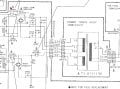
I'm using a good quality step down transformer that lowers the voltage to 110, and have been using the mixer like this without any issues. Its only after I powered both the transformer and the mixer on at the same time that the buzzing occurred. I'm guessing the transformer didnt have enough time to do its job properly and there was a surge into the mixer? Normally I power the transformer on first and then power the mixer on. I'm attaching the service manual if that helps. Thanks for taking the time to answer these queries.
 

Attachments

ericgibbs

Joined Jan 29, 2010
21,637
If I tap on the side of the mixer, the buzzing goes away, but returns shortly thereafter. The LED lights on the mixer also seem to flicker with the buzzing. So I asked AI and it told me to run this test, which I did.
Hi Pat,
I cannot see how a defective rectifier would cause a buzz problem that disappears when you tap the mixer, and thenreappear later on.
Are there any onboard IC's in sockets?
E
Clip:
RectifierEG 2298.jpg section.
 

ericgibbs

Joined Jan 29, 2010
21,637
hi Pat,
Get an electrically insulated rod, say 9 inch or so.

Power Off the Amp, remove the outer cover of the amp, switch ON the power.

Using the rod, Lightly tap and press on different sections of the PCB, near the components and IC's, see if you can induce the buzz, On/Off sound.

Also use the rod to carefully move the ribbon cables near their connectors.

Additionally, check the 'tightness' of any PCB to Chassis grounding screws.

Take care to ensure your personal electrical safety.

Lets us know the test results.
E
 
Last edited:
Thread starter Similar threads Forum Replies Date
PeteHL Technical Repair 0
Top